This 12th article in the series of “Do It Yourself: Electronics”, demonstrates setting up of USART communication with a micro-controller.
<< Previous Article
While trying out the various micro-controller programs, Rohit or for that matter even Pugs had many times faced a dire need for something more than blinking a LED but simple enough to debug their programs – something like printf(). And that brings them to the ubiquitous serial communication over serial port or the USART (Universal Synchronous Asynchronous serial Receiver Transmitter). Though it is vanishing from today’s PCs & laptops, almost every embedded device has it. And so is it with the ATmega16/32 – it has the pins 14 (PD0 / RXD) and 15 (PD1 / TXD) respectively for receiving and transmitting data serially. However, these pins operate at TTL voltage levels or so as to say at 0V & 5V in our case. So, if we want to communicate it with our PC, say over USB, we would need a TTL to USB converter. Figure below shows one such hardware readily available in the market.
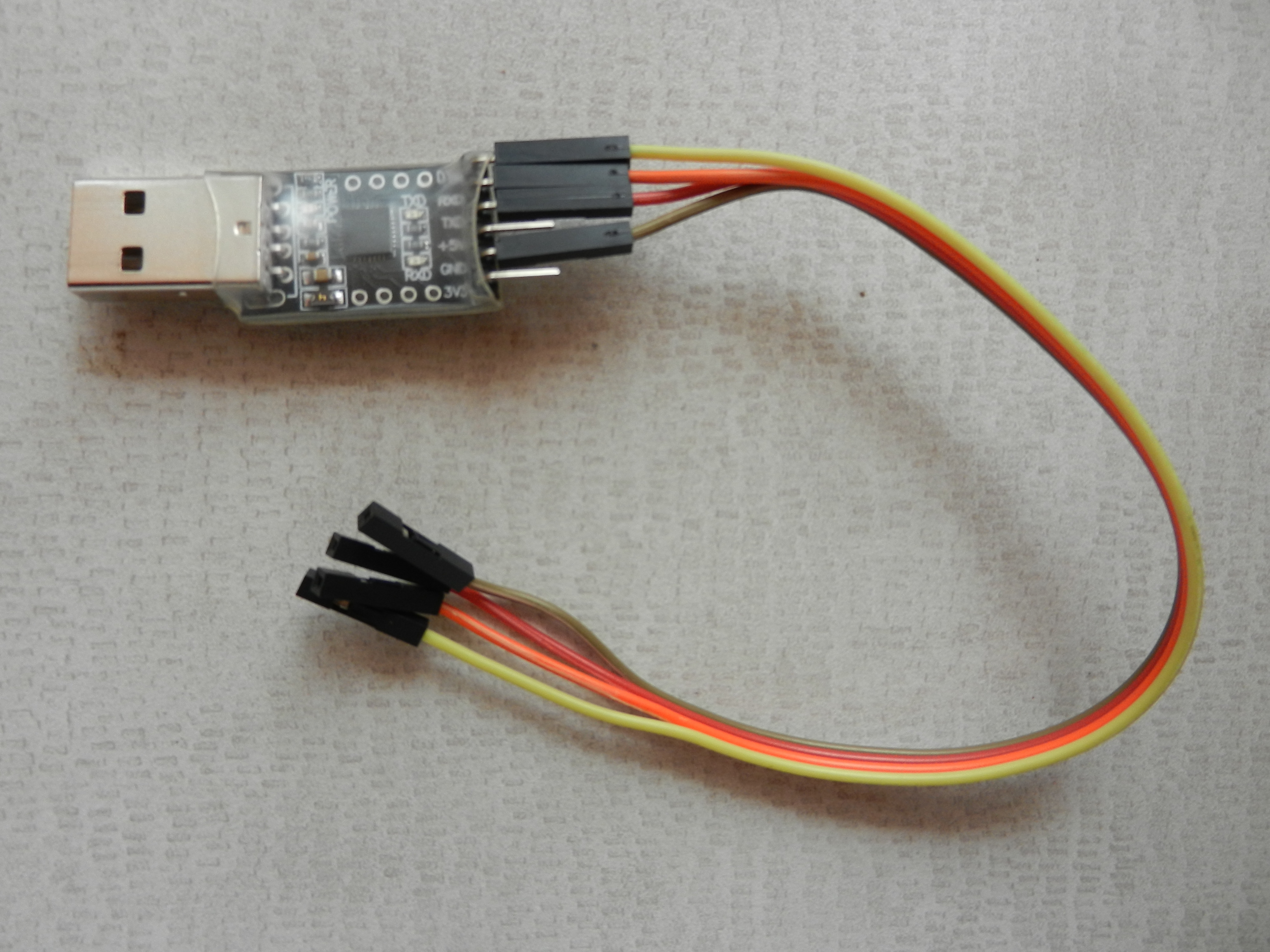
TTL to USB Converter
Equipped with the information above, and a walk through the USART section of ATmega16 datasheet pg 144-171, lead to the following programming conclusions:
- USART needs to be configured for baud rate aka data bit rate, data bit length, stop bit count, parity type
- These configurations are achieved by programming the following registers: UBRRH, UBRRL for baud rate; UCSRB, UCSRC for others
- Data transmission and reception are achieved for every data byte wrote in /read from the USART I/O Data (UDR) register
- Before transmission and reception, the corresponding TXEN and RXEN bit need to be set in UCSRB register
- On completion of transmission and reception, the corresponding TXC and RXC bits in UCSRA register are set
- UDRE bit in UCSRA indicates state of the data register, ‘1’ meaning empty and ready to be written
Having obtained the above information, along with the following baud rate formula (from the ATmega16 datasheet pg 147):
}")
Pugs coded the following serial.c:
#include <avr/io.h>

typedef enum
{
	p_none,
	p_even,
	p_odd
} Parity;

static void set_baud(unsigned long baud)
/*
 * For default of Asynchronous mode and for USART0.
 * For Normal mode: baud = (F_CPU / (16 * (UBRR + 1)))
 */
{
	uint16_t ubrr;

	ubrr = (F_CPU / 16 / baud) - 1;
	UBRRH = (uint8_t)(ubrr >> 8);
	UBRRL = (uint8_t)(ubrr);
}
static void set_format(uint8_t data_bits, Parity parity, uint8_t stop_bits)
{
	uint8_t control = (1 << URSEL);

	switch (data_bits)
	{
		case 5:
			control |= (0b00 << UCSZ0);
			// And, UCSRB &= ~(1 << UCSZ2);
			break;
		case 6:
			control |= (0b01 << UCSZ0);
			// And, UCSRB &= ~(1 << UCSZ2);
			break;
		case 7:
			control |= (0b10 << UCSZ0);
			// And, UCSRB &= ~(1 << UCSZ2);
			break;
		case 8:
		default:
			control |= (0b11 << UCSZ0);
			// And, UCSRB &= ~(1 << UCSZ2);
			break;
		case 9:
			control |= (0b11 << UCSZ0);
			// And, UCSRB |= (1 << UCSZ2);
			break;
	}
	switch (parity)
	{
		case p_none:
		default:
			control |= (0b00 << UPM0);
			break;
		case p_even:
			control |= (0b10 << UPM0);
			break;
		case p_odd:
			control |= (0b11 << UPM0);
			break;
	}
	switch (stop_bits)
	{
		case 1:
		default:
			control |= (0b0 << USBS);
			break;
		case 2:
			control |= (0b1 << USBS);
			break;
	}

	if (data_bits == 9)
		UCSRB |= (1 << UCSZ2);
	else
		UCSRB &= ~(1 << UCSZ2);
	UCSRC = control;
}

static void usart_enable(void)
{
	/* Enable receiver and transmitter */
	UCSRB |= (1 << RXEN) | (1 << TXEN);
}
static void usart_disable(void)
{
	/* Disable receiver and transmitter */
	UCSRB &= ~((1 << RXEN) | (1 << TXEN));
}

void usart_init(unsigned long baud)
{
	set_baud(baud);

	/* Default frame format: 8 data, No Parity, 1 stop bit (8N1) */
	set_format(8, p_none, 1);

	usart_enable();
}
void usart_shut(void)
{
	usart_disable();
}

void usart_byte_tx(uint8_t data)
{
	/* Wait for empty transmit buffer */
	while (!(UCSRA & (1 << UDRE)))
		;
	/* Put data into buffer, sends the data */
	UDR = data;
}
int usart_byte_available(void)
{
	return (UCSRA & (1 << RXC));
}
uint8_t usart_byte_rx(void)
{
	/* Wait for data to be received */
	while (!(UCSRA & (1 << RXC)))
		;
	/* Get and return received data from buffer */
	return UDR;
}
void usart_tx(char *str)
{
	while (*str)
	{
		usart_byte_tx(*str++);
	}
}
void usart_rx(char *str, int max_len)
{
	int i;

	for (i = 0; i < max_len - 1; i++)
	{
		str[i] = usart_byte_rx();
		if (str[i] == '\n')
			break;
	}
	str[i] = 0;
}

int main(void)
{
	char c;

	usart_init(38400);

	usart_byte_rx(); // Waiting for a character, typically an
	usart_tx("Welcome to SysPlay's character echoer\r\n");

	while (1)
	{
		usart_tx("SysPlay> ");
		c = usart_byte_rx();
		usart_tx("You gave: ");
		usart_byte_tx(c);
		usart_tx("\r\n");
	}

	usart_shut();

	return 0;
}
Then, Pugs compiled the program as follows (as in the previous articles):
$ avr-gcc -mmcu=atmega16 -DF_CPU=1000000 -Os serial.c -o serial.elf
$ avr-objcopy -O ihex serial.elf serial.hex
And finally, downloaded the serial.hex into the ATmega16 with J1 shorted (same as in the previous articles), using the following command:
$ avrdude -c ponyser -P /dev/ttyUSB0 -p m16 -U flash:w:serial.hex:i
Pugs then connected the USB to TTL converter to his laptop on the USB side, and the RX, TX, GND pins of the USB to TTL converter to the corresponding pins of the micro-controller. And started the serial application minicom as root on his laptop as follows:
# minicom -D /dev/ttyUSB1 -b 38400 -o
Note that Pugs’ TTL to USB connector shows up as /dev/ttyUSB1 on his laptop. In case, yours is different, use that instead. And as usual, it didn’t work in the first shot, even though he removed the jumper J1. After some googling, Pugs realized that it should have been a common sense to connect the RXD of the micro-controller to the TX of the TTL to USB converter and TXD of the micro-controller to the RX of the TTL to USB converter, rather than TXD to TX and RXD to RX, because data transmitted from micro-controller would be received by the USB and vice versa. So, correcting the connections, Pugs got the input character echoing back on the serial console. To see what he was typing, Pugs typed Ctrl-A E on minicom. And, to quit from minicom, Pugs typed Ctrl-A Q.
Given the basic setup and operation of USART achieved, watch out for how Pugs designs a library to do some fancy debugging.
Next Article >>