This 24th article in the series of “Do It Yourself: Electronics”, does level inversion of a given input using IC 555.
By now, Pugs had tried two of the three operating modes of 555 – astable and monostable. How do you think, one can stop Pugs from trying the third one? So, here is his experiment to try the bistable mode, i.e. in which both high & low outputs are stable, meaning the circuit remains in the state it is in, unless triggered externally to go otherwise. A typical usage of this could be a NOT gate kind of level inversion by simply tying the input to both the trigger pin 2 and threshold pin 6.
Below is the schematic, and the breadboard connections made by Pugs with input from a pulled up switch:
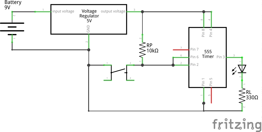
Bistable (Level Inversion) using 555 (Schematic)

Bistable (Level Inversion) using 555 (Breadboard)
This configuration is also referred as inverting Schmitt Trigger, and very useful in boosting fainting digital signals (though inverted) and removing noise. Putting two of such would make it non-inverting. But how does it boost or remove noise? Let’s assume Vcc = 5V. Say logic 1 (5V) signal is fainting to 4V. As it is still above 2/3 of Vcc (3.33V), the above circuitry will hit the threshold and output would be 0V (boosted logic 0). Similarly, if logic 0 (0V) is fainitng to 1V, still less than 1/3 of Vcc (1.67V), it would hit the trigger and output would be 5V (boosted logic 1). And in both cases, the output can be fed into another such circuitry to get the input boosted without inversion.
The following video clip shows the immediate output level inversion. Specifically, observe that LED is off (low output) on switch released (i.e. high input) and LED is on (high output) on switch pressed (i.e. low input).
Interestingly, the bistable output can also be obtained using two separate switches, providing a possibility of using the setup in a system, controlled by switches. Here are two possible schematics for the same:
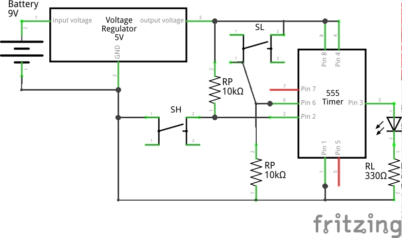
Bistable (Schmitt Trigger Circuit 1) using 555 (Schematic)
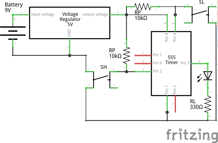
Bistable (Schmitt Trigger Circuit 2) using 555 (Schematic)
In both the above circuits, pressing switch SH will take the Vo output high, and pressing the switch SL will take the Vo output low. The only difference being as how is the Vo output brought low – in the first one using the trigger pin 6 and in the second one using the reset pin 4.