This 9th article in the series of “Do It Yourself: Electronics”, programs a micro-controller without a hardware programmer.
In playing around with DIY electronics, Pugs has developed enough confidence to share his knowledge with his juniors. So, in one such occasion, he decided to give a try to program a micro-controller, as part of the electronics hobby club. There have been many hobbyist micro-controllers, like 8051, PIC, AVR, … and an equivalent or more varieties of hardware programmers to program them. However, Pugs’ goal was different – how can a DIY electronics learner, one as he is, do program a micro-controller in the simplest possible way with no unknown pieces of hardware, meaning no external hardware programmers. First fundamental question was if that was even possible.
“Hey Pugs, seems like it can be achieved with AVR controllers – they have a simple serial programming mechanism using their MOSI, MISO, SCK lines”, exclaimed his junior Vinay, while going through the AVR ATmega16 datasheet pg 273-277.
“Yes, seems possible, at least on the AVR side – we may just have to figure out, how to control these lines from a laptop”, asserted Pugs, reviewing the same.
“Can’t we use serial?”, ask Vinay.
“Yes, but our laptops don’t have a serial – hopefully USB to Serial converters would work”, replied Pugs.
“If it works, it would be great. We can then just connect the various serial port lines to the corresponding ATmega16 lines, and then write an application on laptop to download a ‘blink led’ program into the ATmega16”, supported Vinay.
“Regarding the application, we may not have to write one, as there is already one open source application called avrdude, specially for downloading or flashing programs into AVRs. We may just have to configure it properly”, replied Pugs.
“O! That’s good.”
“However, connecting the lines of ATmega16 to serial port may not be straight forward.”
“Why? That looks simpler than the flashing part.”
“Ya! but the challenge is that serial port lines operate on +/-12V – +12V being logic 0 and -12V being logic 1. And, micro-controllers understand 0/+5V – 0 being logic 0V and +5V being logic 1.”
“Oh! I didn’t know that there are things where 0 and 1 are not just 0V and 5V. Then, it might not be possible to connect them, right?”
“Don’t give up that easy. Where there is a problem, there would be a solution. Possibly there would be some way to do the proper voltage translations.”
So, they explored further about the same and figured out that ICs like MAX232 are meant exactly for such purposes. MAX232 datasheet gave them the connection details. Using that, they set up the ATmega16 and MAX232 connections, as shown in the schematic and breadboard diagram below. They also connected an LED through a resistor to port pin B0 for “blink led” program. Also, they set up the reset circuitry using the pull-up resistor and the jumper J1, as reset needs to be pulled low for downloading the program into ATmega16, and needs to be set high for running the program. So, J1 would be shorted, before starting the programming, and opened for running the flashed program.
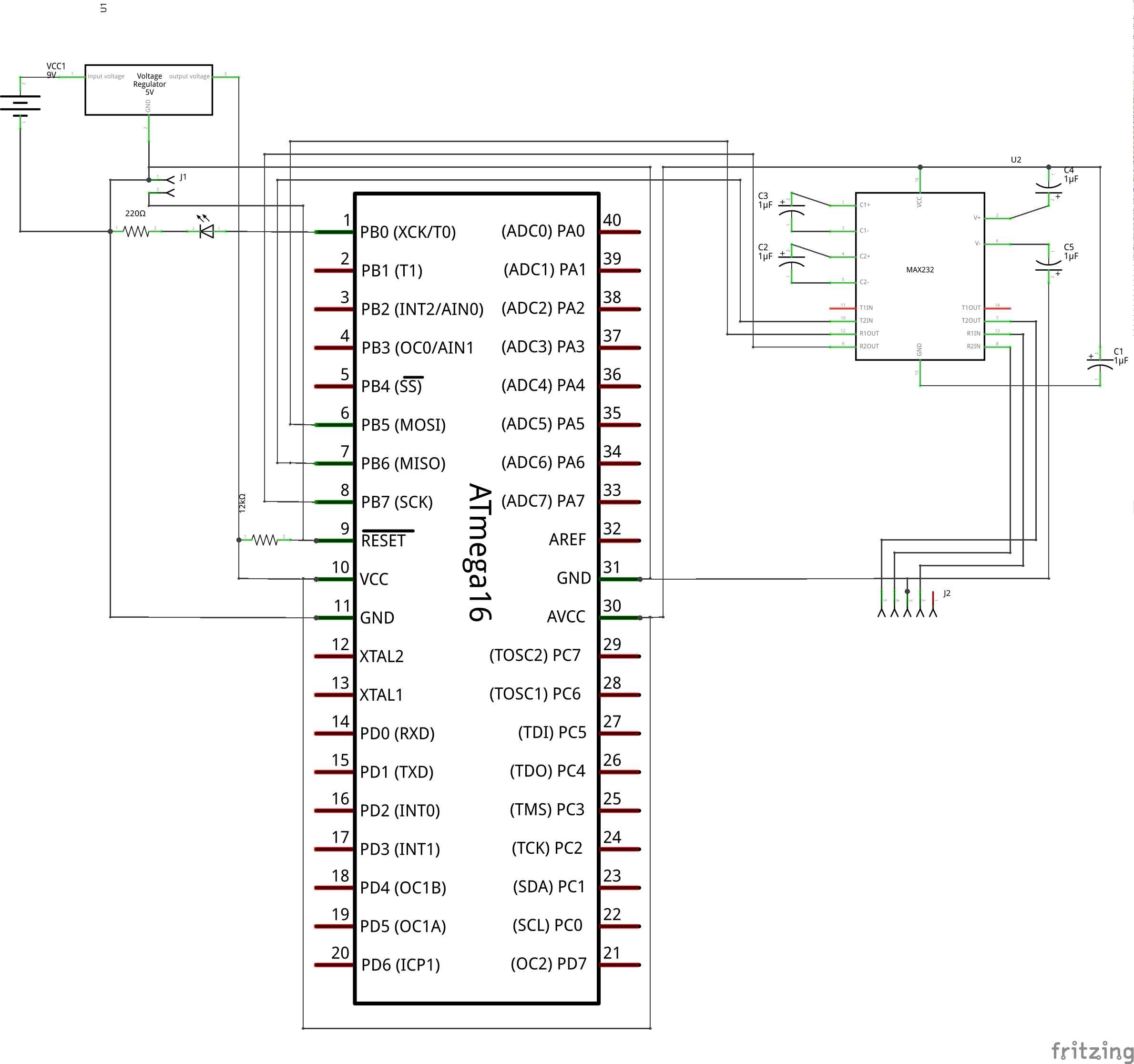
AVR Programming Schematic
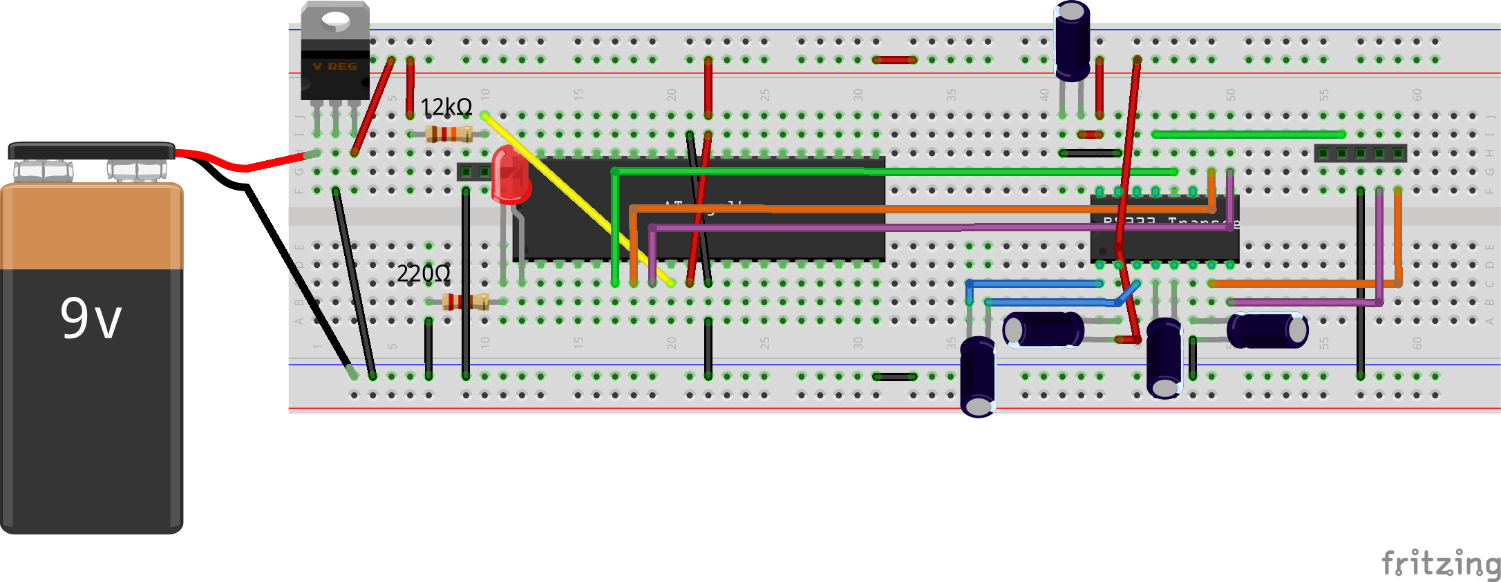
AVR Programming Bread Board Connections
“Aha! That’s cool. So, now we have the jumper J2 to connect our ATmega16 to our laptop over the serial port. But how do we decide, which lines to connect to what?”, doubted Vinay.
“That should be simpler. Let’s open the avrdude‘s configuration file, and look for ponyser section, which is the mode we are going to use for flashing our program”, suggested Pugs.
The following is what they obtained from the avrdude.conf file (typically located under /etc/avrdude/ in Linux):
programmer
  id    = "ponyser";
  desc  = "design ponyprog serial, reset=!txd sck=rts mosi=dtr miso=cts";
  type  = "serbb";
  connection_type = serial;
  reset = ~3;
  sck   = 7;
  mosi  = 4;
  miso  = 8;
;
Based on this, they figured out and connected the following serial port line connections with the jumper J2 from left to right in the schematic: CTS (pin 8), RTS (pin 7), GND (pin 5), DTR (pin 4), using the jumper cables. And, finally powered the whole circuitry with 5V from an LM7805 & 9V battery, as shown in the schematic and breadboard diagram above.
Vinay got the following blink_led.c program coded in C:
/* Toggles the LED connected at PB0 at 1Hz */

#include <avr/io.h>
#include <util/delay.h>

void init_io(void)
{
	// 1 = output, 0 = input
	DDRB |= (1 << DDB0);
}

int main(void)
{
	init_io();

	while (1)
	{
		PORTB |= (1 << PB0);
		_delay_ms(500);
		PORTB &= ~(1 << PB0);
		_delay_ms(500);
	}

	return 0;
}
Alongwith, he installed the AVR toolchain and compiled the program as follows:
$ avr-gcc -mmcu=atmega16 -DF_CPU=1000000 -Os blink_led.c -o blink_led.elf
$ avr-objcopy -O ihex blink_led.elf blink_led.hex
Why the F_CPU=1000000? As Vinay figured out from the ATmega16 datasheet pg 260-261, that with the default fuse settings of the ATmega16, it runs on a 1MHz clock.
And finally, they downloaded the blink_led.hex into the ATmega16 (with J1 shorted), using the following command:
$ avrdude -c ponyser -P /dev/ttyUSB0 -p m16 -U flash:w:blink_led.hex:i
“Hey Pugs, avrdude says programmed successfully. But no LED blink. What could be wrong?”
“Did you remove the short from J1?”
“Aha! No. So, it is still in downloading mode.”
Vinay removes the short and viola LED connected to port pin B0 starts blinking with a 1Hz frequency.
Enhancement
Interestingly, on his later explorations, Pugs figured out that you don’t even need the MAX232 & related circuitry to do the flashing of an AVR. One can directly connect the MISO line to the CTS pin, as this is input to the serial. And, the other two lines (MOSI to DTR, SCK to RTS) can be connected each through a 22K resistor, thus limiting the voltage into the ATmega16. See the schematic and breadboard diagram below.
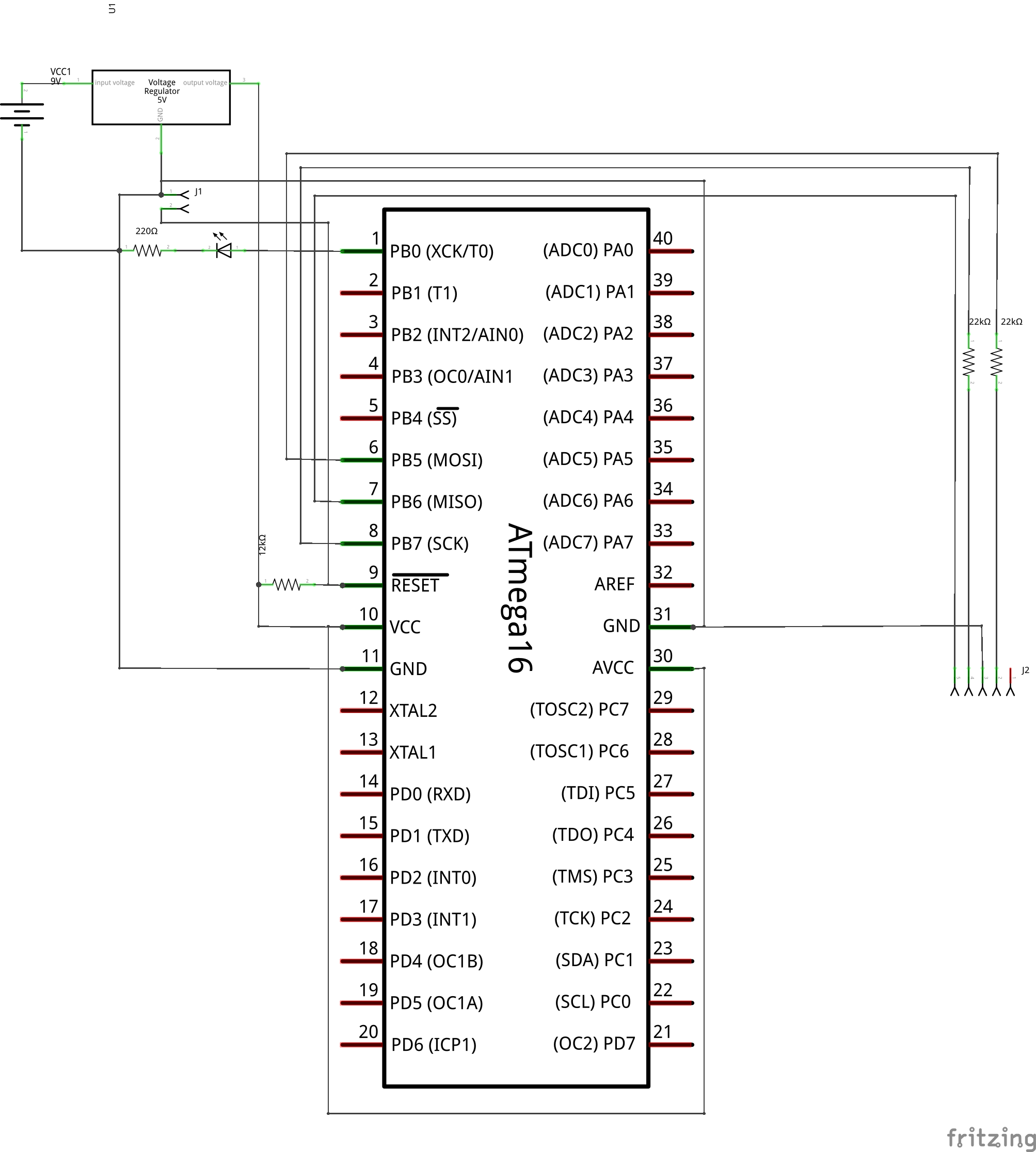
AVR Programming Simplified Schematic
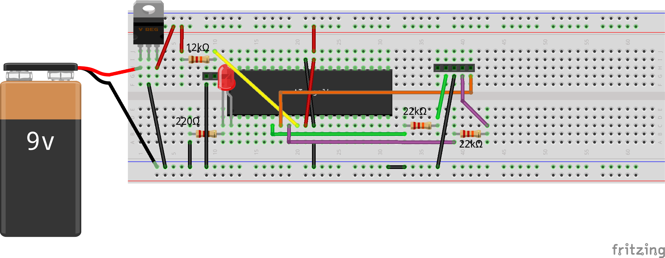
AVR Programming Simplified Bread Board Connections
But now, the logic is reversed on all the 3 lines, and hence an another entry, with values inverted from the ponyser entry, say ponyseri, has to be added in the avrdude.conf, as follows:
programmer
  id    = "ponyseri";
  desc  = "design ponyprog serial, reset=txd sck=!rts mosi=!dtr miso=!cts";
  type  = "serbb";
  connection_type = serial;
  reset = 3;
  sck   = ~7;
  mosi  = ~4;
  miso  = ~8;
;
And, then to be used in the avrdude command as follows:
$ avrdude -c ponyseri -P /dev/ttyUSB0 -p m16 -U flash:w:blink_led.hex:i
The author is a hobbyist in open source hardware and software, with a passion for mathematics, and philosopher in thoughts. A gold medallist from the Indian Institute of Science, Linux, mathematics and knowledge sharing are few of his passions. He experiments with Linux and embedded systems to share his learnings through his weekend workshops. Learn more about him and his experiments at https://sysplay.in.


Pingback: Multi-colour using RGB LED | Playing with Systems
Pingback: Digital to Analog Conversion using a micro-controller | Playing with Systems