This eighth article, which is part of the series on Linux device drivers, continues on talking about accessing hardware in Linux.
Second day in the Linux device drivers laboratory was expected to be quite different from the typical software oriented classes. Apart from accessing & programming the architecture-specific I/O mapped hardware in x86, it had lot to offer for first timers in reading hardware device manuals (commonly referred as data-sheets) and to understand them for writing device drivers.
Contrast this with the previous laboratory session, which taught about the generic architecture-transparent hardware interfacing. It was all about mapping and accessing memory-mapped devices in Linux, without any device specific detail.
x86-specific hardware interfacing
Unlike most other architectures, x86 has an additional hardware accessing mechanism through a direct I/O mapping. It is a direct 16-bit addressing scheme and doesn’t need a mapping to virtual address for its accessing. These addresses are referred to as port addresses, or in short – ports. As x86 has this as an additional accessing mechanism, it calls for additional set of x86 (assembly/machine code) instructions. And yes, there are the input instructions inb, inw, inl for reading an 8-bit byte, a 16-bit word, and a 32-bit long word respectively, from the I/O mapped devices through the ports. And the corresponding output instructions are outb, outw, outl, respectively. And the equivalent C functions/macros are as follows (available through the header <asm/io.h>):
u8 inb(unsigned long port);
u16 inw(unsigned long port);
u32 inl(unsigned long port);
void outb(u8 value, unsigned long port);
void outw(u16 value, unsigned long port);
void outl(u32 value, unsigned long port);
The basic question may arise, as to which all devices are I/O mapped and what are the port addresses of these devices. The answer is pretty simple. As per x86-specific, all these devices & their mappings are x86 standard and hence pre-defined. Figure 13 shows a snippet of these mappings through the kernel window /proc/ioports. The listing includes pre-defined DMA, timer, RTC, serial, parallel, PCI bus interfaces to name a few.
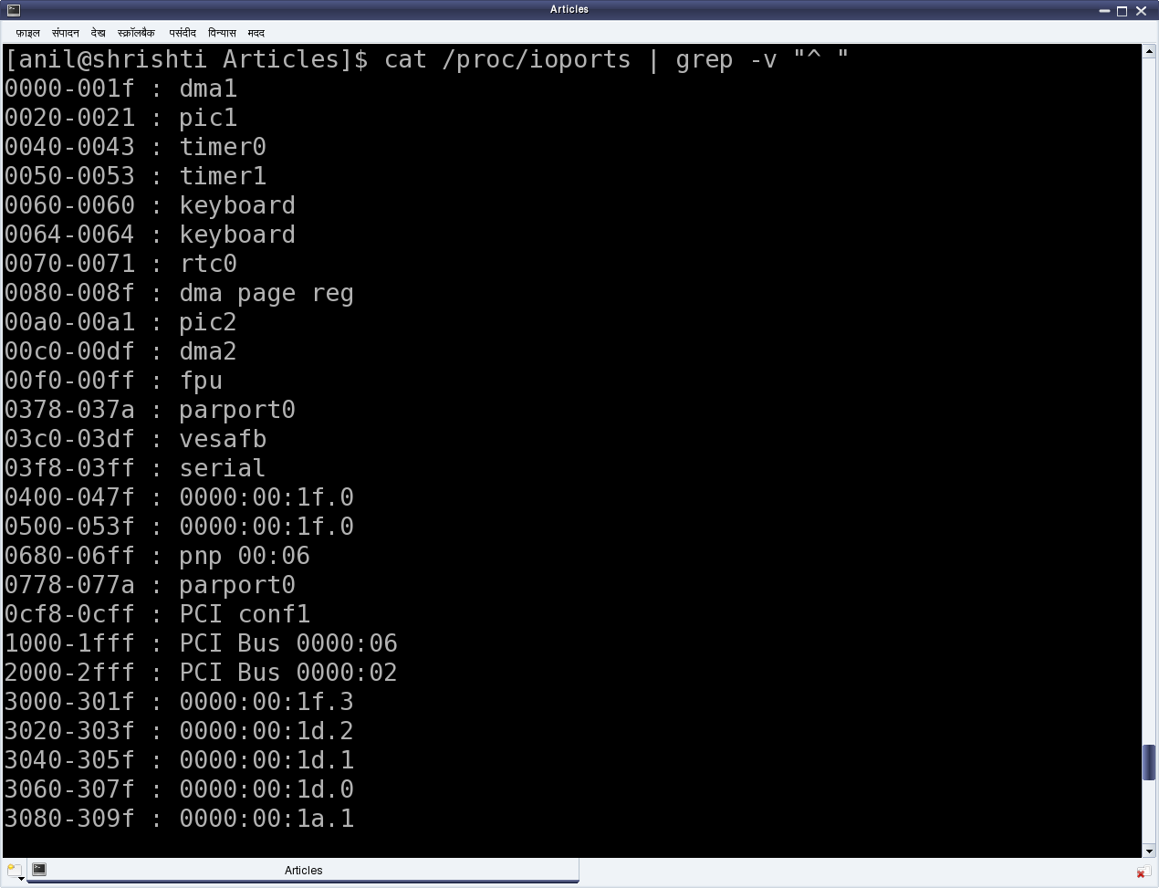
Figure 13: x86-specific I/O ports
Simplest the serial on x86 platform
For example, the first serial port is always I/O mapped from 0x3F8 to 0x3FF. But what does this mapping mean? What do we do with this? How does it help us to use the serial port?
That is where a data-sheet of the device controlling the corresponding port needs to be looked up. Serial port is controlled by the serial controller device, commonly known as an UART (Universal Asynchronous Receiver/Transmitter) or at times a USART (Universal Synchronous/Asynchronous Receiver/Transmitter). On PCs, the typical UART used is PC16550D. The data-sheet (uart_pc16550d.pdf) for the same has also been included in the self-extracting LDDK-Package.sh, used for the Linux device driver kit. Figure 14 shows the relevant portion of it.
In general, from where & how do we get these device data-sheets? Typically, an on-line search with the corresponding device number should yield their data-sheet links. And how does one get the device number? Simple, by having a look at the device. If it is inside a desktop, open it up and check it out. Yes, this is the least you may have to do to get going with the hardware for writing device drivers. Assuming all this hacking has been done, it is time to peep into the data-sheet of UART PC16550D.
For a device driver writer, the usual sections of interest in a data-sheet are the ones related to registers of the device. Why? As, it is these registers, which a device driver writer need to read from and/or write in to finally use the device. Page 14 of the data-sheet (also shown in Figure 14) shows the complete table of all the twelve 8-bit registers present in the UART PC16550D. Each of the 8 rows corresponds to the respective bit of the registers. Also, note that the register addresses start from 0 and goes till 7. The interesting thing to note about this is that a data-sheet always gives the register offsets, which then need to be added to the base address of the device, to get the actual register addresses. Who decides the base address and where is it obtained from? Base addresses are typically board/platform specific, unless they are dynamically configurable like in the case of PCI devices. In the case here, i.e. serial device on x86, it is dictated by the x86 architecture – and that is what precisely was the starting serial port address mentioned above – 0x3F8. And the eight register offsets 0 to 7 are the ones exactly mapping to the eight port addresses 0x3F8 to 0x3FF. So, these are the actual addresses to be read or written for reading or writing the corresponding serial registers, to achieve the desired serial operations, as per the register descriptions.
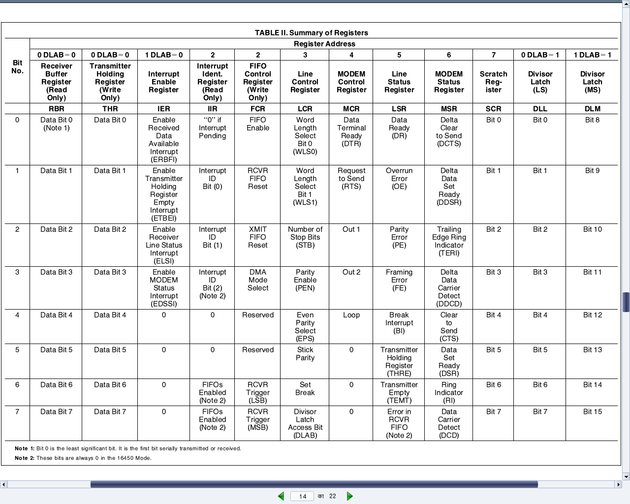
Figure 14: Registers of UART PC16550D
All the serial register offsets and the register bit masks are defined in the header <linux/serial_reg.h>. So, rather than hard coding these values from the data-sheet, the corresponding macros could be used instead. All the following code uses these macros along with the following:
#define SERIAL_PORT_BASE 0x3F8
Operating on the device registers
To summarize all these decoding of UART PC16550D data-sheet, here are a few examples of how to do read and write operations of the serial registers and their bits.
Reading and writing the “Line Control Register (LCR)”:
u8 val;

val = inb(SERIAL_PORT_BASE + UART_LCR /* 3 */);
outb(val, SERIAL_PORT_BASE + UART_LCR /* 3 */);
Setting and clearing the “Divisor Latch Access Bit (DLAB)” in LCR:
u8 val;

val = inb(SERIAL_PORT_BASE + UART_LCR /* 3 */);

/* Setting DLAB */
val |= UART_LCR_DLAB /* 0x80 */;
outb(val, SERIAL_PORT_BASE + UART_LCR /* 3 */);

/* Clearing DLAB */
val &= ~UART_LCR_DLAB /* 0x80 */;
outb(val, SERIAL_PORT_BASE + UART_LCR /* 3 */);
Reading and writing the “Divisor Latch”:
u8 dlab;
u16 val;

dlab = inb(SERIAL_PORT_BASE + UART_LCR);
dlab |= UART_LCR_DLAB; // Setting DLAB to access Divisor Latch
outb(dlab, SERIAL_PORT_BASE + UART_LCR);

val = inw(SERIAL_PORT_BASE + UART_DLL /* 0 */);
outw(val, SERIAL_PORT_BASE + UART_DLL /* 0 */);
Blinking an LED
To get a real experience of the low-level hardware access and Linux device drivers, the best way would be to play with the Linux device driver kit (LDDK). However, just for the feel of low-level hardware access, a blinking light emitting diode (LED) may be tried as follows:
- Connect a light emitting diode (LED) with a 330 ohm resistor in series across the pin 3 (Tx) & pin 5 (Gnd) of the DB9 connector of your PC.
- Pull up & down the transmit (Tx) line with a 500 ms delay, by loading the blink_led driver using insmod blink_led.ko, and then unloading the driver using rmmod blink_led, before reloading.
Below is the blink_led.c, to be compiled into the blink_led.ko driver, by running make using the usual driver Makefile:
#include <linux/module.h>
#include <linux/version.h>
#include <linux/types.h>
#include <linux/delay.h>
#include <asm/io.h>

#include <linux/serial_reg.h>

#define SERIAL_PORT_BASE 0x3F8

int __init init_module()
{
	int i;
	u8 data;

	data = inb(SERIAL_PORT_BASE + UART_LCR);
	for (i = 0; i < 5; i++)
	{
		/* Pulling the Tx line low */
		data |= UART_LCR_SBC;
		outb(data, SERIAL_PORT_BASE + UART_LCR);
		msleep(500);
		/* Defaulting the Tx line high */
		data &= ~UART_LCR_SBC;
		outb(data, SERIAL_PORT_BASE + UART_LCR);
		msleep(500);
	}
	return 0;
}

void __exit cleanup_module()
{
}

MODULE_LICENSE("GPL");
MODULE_AUTHOR("Anil Kumar Pugalia <email@sarika-pugs.com>");
MODULE_DESCRIPTION("Blinking LED Hack");
Summing up
Are you wondering as where has Shweta gone today? She has bunked all the classes. Watch out for the next article to find out why.
Notes
- The above example is to demonstrate how bare bone easy the low level access could get. However, to make it more perfect, one should use the APIs request_region() and release_region(), respectively before and after the accesses of the I/O port addresses, respectively to acquire and release the range of I/O port addresses to access.
- Also, you might have observed that there is no module_init() & module_exit() in the above driver. But nonetheless, insmod & rmmod do work. How is that? That is because init_module() & cleanup_module() are the predefined names for the constructor & the destructor, respectively. Hence, you do not need module_init() & module_exit() to translate your other function names to these predefined ones. Caution: Since kernel 2.6 onwards, if you are building the driver into the kernel, you should define your own function names & use module_init() & module_exit().
The author is a hobbyist in open source hardware and software, with a passion for mathematics, and philosopher in thoughts. A gold medallist from the Indian Institute of Science, Linux, mathematics and knowledge sharing are few of his passions. He experiments with Linux and embedded systems to share his learnings through his weekend workshops. Learn more about him and his experiments at https://sysplay.in.


Pingback: Generic Hardware Access in Linux | Playing with Systems
Pingback: I/O Control in Linux | Playing with Systems
Hi Anil,
I have an intel-atom board, I tried cat /proc/ioports | grep -v “^ ” but it displayed only 3 items
0000-0cf7 : PCI BUS 0000:00
0cf8-0cff : PCI conf1
0d00-ffff : PCI Bus 0000:00
The serial entry is under the first PCI Bus with address range 03f8-03ff. How could I interact the serial with this type of interface?
Would it be the same also when interfacing with GPIOs?
Thanks
gee
I think that should be fine. You may be able to interact with serial as mentioned in the above article. Try it out & provide your feedback. Also, for GPIOs, you need to check out, if they are on ioports or iomem.
Hi Anil,
Thanks for your reply. I’ve tried to look into my intel board schematic and can’t find any UART chip. I believed my UART is directly connected to PCI bus, if this is the case how can I interact with it?
Also, if the GPIO also is in PCI bus, how can I map it to physical port pins of my board?
I appreciate your help on this.
Thanks
gee
In that case, go through PCI. Check out its listing using lspci and lspci -v
Hi Anil,
Thanks for your reply.
I’ve look into lspci and lspci -v and even lspci -vvv
There are lots of information, don’t know which one I should start looking.
There is a serial bus and smbus entry like:
00:1a.0 Serial bus controller[0c80]: Intel …
Interrupt: pin A routed to IRQ 255
Region 0: Memory …
Region 2: Memory…
Capabilities:
Kernel driver in use: pwm-lpss
00:1f.1 SMBUS:…
But no GPIO or specifically UART entry. How can I talk to GPIO or UART on this setup?
Don’t try so many v’s in lspci – that would be too much info. Just try lspci -v and look for the 3f8, … addresses (you were mentioning above) in the output. Or, just paste your just “lspci” output here.
Hi Anil
Thanks for putting all those details in so lucid way!
Regards
Sandip
You are welcome
Hi Anil,
Thank you for your reply.
It looks like I can no longer reply to your last post, no Reply link, so I’m starting a new thread here.
Here is my lspci output:
00:00.0 Host bridge: Intel Corporation 82X38/X48 Express DRAM Controller
00:01.0 PCI bridge: Intel Corporation 82X38/X48 Express Host-Primary PCI Express Bridge
00:06.0 PCI bridge: Intel Corporation 82X38/X48 Express Host-Secondary PCI Express Bridge
00:1a.0 USB controller: Intel Corporation 82801I (ICH9 Family) USB UHCI Controller #4 (rev 02)
00:1a.1 USB controller: Intel Corporation 82801I (ICH9 Family) USB UHCI Controller #5 (rev 02)
00:1a.2 USB controller: Intel Corporation 82801I (ICH9 Family) USB UHCI Controller #6 (rev 02)
00:1a.7 USB controller: Intel Corporation 82801I (ICH9 Family) USB2 EHCI Controller #2 (rev 02)
00:1b.0 Audio device: Intel Corporation 82801I (ICH9 Family) HD Audio Controller (rev 02)
00:1c.0 PCI bridge: Intel Corporation 82801I (ICH9 Family) PCI Express Port 1 (rev 02)
00:1c.5 PCI bridge: Intel Corporation 82801I (ICH9 Family) PCI Express Port 6 (rev 02)
00:1d.0 USB controller: Intel Corporation 82801I (ICH9 Family) USB UHCI Controller #1 (rev 02)
00:1d.1 USB controller: Intel Corporation 82801I (ICH9 Family) USB UHCI Controller #2 (rev 02)
00:1d.2 USB controller: Intel Corporation 82801I (ICH9 Family) USB UHCI Controller #3 (rev 02)
00:1d.7 USB controller: Intel Corporation 82801I (ICH9 Family) USB2 EHCI Controller #1 (rev 02)
00:1e.0 PCI bridge: Intel Corporation 82801 PCI Bridge (rev 92)
00:1f.0 ISA bridge: Intel Corporation 82801IR (ICH9R) LPC Interface Controller (rev 02)
00:1f.2 SATA controller: Intel Corporation 82801IR/IO/IH (ICH9R/DO/DH) 6 port SATA Controller [AHCI mode] (rev 02)
00:1f.3 SMBus: Intel Corporation 82801I (ICH9 Family) SMBus Controller (rev 02)
01:00.0 VGA compatible controller: NVIDIA Corporation G96GL [Quadro FX 580] (rev a1)
04:00.0 Ethernet controller: Broadcom Corporation NetXtreme BCM5754 Gigabit Ethernet PCI Express (rev 02)
Thanks
What are these PCI Express Port 1 & Port 6? Did you check for 3f8 in the output of lspci -v?
Thank you Anil for your reply.
Yes, I looked into it and both Port 1 and 6 does have a long range in memory and I/O. I’m not sure where to look at, would it be in I/O behind bridge, memory behind bridge or the prefetchable memory.
Below is the output of lspci -v and just pasted the PCI bridge primary and secondary and the two ports (1 & 6) here.
00:01.0 PCI bridge: Intel Corporation 82X38/X48 Express Host-Primary PCI Express Bridge (prog-if 00 [Normal decode])
Flags: bus master, fast devsel, latency 0, IRQ 24
Bus: primary=00, secondary=01, subordinate=01, sec-latency=0
I/O behind bridge: 0000d000-0000dfff
Memory behind bridge: fa000000-fdefffff
Prefetchable memory behind bridge: 00000000c0000000-00000000dfffffff
Capabilities: [88] Subsystem: Dell 82X38/X48 Express Host-Primary PCI Express Bridge
Capabilities: [80] Power Management version 3
Capabilities: [90] MSI: Enable+ Count=1/1 Maskable- 64bit-
Capabilities: [a0] Express Root Port (Slot+), MSI 00
Capabilities: [100] Virtual Channel
Capabilities: [140] Root Complex Link
Kernel driver in use: pcieport
Kernel modules: shpchp
00:06.0 PCI bridge: Intel Corporation 82X38/X48 Express Host-Secondary PCI Express Bridge (prog-if 00 [Normal decode])
Flags: bus master, fast devsel, latency 0, IRQ 25
Bus: primary=00, secondary=02, subordinate=02, sec-latency=0
Capabilities: [88] Subsystem: Dell 82X38/X48 Express Host-Secondary PCI Express Bridge
Capabilities: [80] Power Management version 3
Capabilities: [90] MSI: Enable+ Count=1/1 Maskable- 64bit-
Capabilities: [a0] Express Root Port (Slot+), MSI 00
Capabilities: [100] Virtual Channel
Capabilities: [140] Root Complex Link
Kernel driver in use: pcieport
Kernel modules: shpchp
00:1c.0 PCI bridge: Intel Corporation 82801I (ICH9 Family) PCI Express Port 1 (rev 02) (prog-if 00 [Normal decode])
Flags: bus master, fast devsel, latency 0, IRQ 26
Bus: primary=00, secondary=03, subordinate=03, sec-latency=0
I/O behind bridge: 00001000-00001fff
Memory behind bridge: f9f00000-f9ffffff
Prefetchable memory behind bridge: 00000000f0000000-00000000f01fffff
Capabilities: [40] Express Root Port (Slot+), MSI 00
Capabilities: [80] MSI: Enable+ Count=1/1 Maskable- 64bit-
Capabilities: [90] Subsystem: Dell 82801I (ICH9 Family) PCI Express Port 1
Capabilities: [a0] Power Management version 2
Capabilities: [100] Virtual Channel
Capabilities: [180] Root Complex Link
Kernel driver in use: pcieport
Kernel modules: shpchp
00:1c.5 PCI bridge: Intel Corporation 82801I (ICH9 Family) PCI Express Port 6 (rev 02) (prog-if 00 [Normal decode])
Flags: bus master, fast devsel, latency 0, IRQ 27
Bus: primary=00, secondary=04, subordinate=04, sec-latency=0
I/O behind bridge: 00002000-00002fff
Memory behind bridge: f9e00000-f9efffff
Prefetchable memory behind bridge: 00000000f0200000-00000000f03fffff
Capabilities: [40] Express Root Port (Slot+), MSI 00
Capabilities: [80] MSI: Enable+ Count=1/1 Maskable- 64bit-
Capabilities: [90] Subsystem: Dell 82801I (ICH9 Family) PCI Express Port 6
Capabilities: [a0] Power Management version 2
Capabilities: [100] Virtual Channel
Capabilities: [180] Root Complex Link
Kernel driver in use: pcieport
Kernel modules: shpchp
Thank you Anil for your help.
These seemed promising but none of them shows a range which could include 0x3f8. Interestingly, no listing in the second one. Can you check “lspci -vvv | grep 3f8”? Also, can you share output of “cat /proc/ioports”?
Hi Anil,
Nothing is displayed with lspci -vvv | grep 3f8
And here is the output of the ioports, serial is present on 03f8-03ff address under pci bus.
:$ cat /proc/ioports
0000-0cf7 : PCI Bus 0000:00
0000-001f : dma1
0020-0021 : pic1
0040-0043 : timer0
0050-0053 : timer1
0060-0060 : keyboard
0061-0061 : PNP0800:00
0064-0064 : keyboard
0070-007f : rtc0
0080-008f : dma page reg
00a0-00a1 : pic2
00c0-00df : dma2
00f0-00ff : PNP0C04:00
00f0-00ff : fpu
0378-037a : parport0
037b-037f : parport0
03c0-03df : vesafb
03f8-03ff : serial
0778-077a : parport0
0800-0803 : ACPI PM1a_EVT_BLK
0804-0805 : ACPI PM1a_CNT_BLK
0808-080b : ACPI PM_TMR
0810-0815 : ACPI CPU throttle
0820-082f : ACPI GPE0_BLK
0830-0833 : iTCO_wdt.0.auto
0860-087f : iTCO_wdt.0.auto
0880-08bf : gpio_ich.1.auto
0880-08bf : 0000:00:1f.0
0880-08af : gpio_ich
08b0-08bf : gpio_ich
0c00-0c7f : pnp 00:00
0cf8-0cff : PCI conf1
0d00-ffff : PCI Bus 0000:00
Thanks for your help.
gee
As per this, you have to operate as per the above article only. The UART may not be external chip, but it seems to be exposed as in the traditional x86 systems.
Did you try the above article on your system? What is the behaviour?