Tag Archives: Breadboard

Water Level Indicator

This 4th article in the series of “Do It Yourself: Electronics”, takes you through using a bipolar junction transistor (BJT), as an electronic switch.

<< Previous Article

Pugs came out of the “Electronics Fundamentals” class, all loaded with internal details of a transistor. He was lost in his own world, when he crossed ways with Surya coming out of his class. Surya called Pugs, without any response. So, he came close and shook Pugs, “Hey Pugs! Where are you?”

Pugs, as if he woke up from deep sleep, “Hey! What happened? Where are you going?”

“Where were you lost? Whom were you remembering? Shall I call Simi?”

“Hey! Shut up yaar. Where did she come in between? I was thinking of how to use the transistors in a practical way”, replied Pugs showing anger.

“Okay. Okay. Cool down. I was just joking. So, today your class was about transistors.”

“Yes.”

“Last time when you went to buy some components, I asked you to get four BC546 transistors, right?”

“Yes. I got them.”

“So now, I think is the time to experiment with them, to bring you back from the lost world.”

“O Great! But you know what, if I remember correct, the shopkeeper didn’t have BC546, and so he gave some other number, saying that is equivalent.”

“Which number?”

“Not really sure.”

“No probs. Let’s go to your room and check it out.”

Both Surya and Pugs walks down to Pugs’ room.

Pugs took out the transistors, trying to check the number written on them.

“Looks like BC548. Can you check, Surya?”

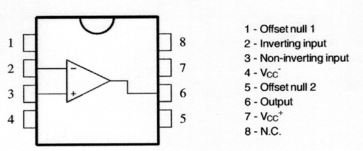
“Yes it is BC548. That’s fine. In fact, BC546 & BC547 are same as BC548, except that they have higher break down voltages. Moreover, there are other variants as well, like BC549 – a low noise variant, BC550 – with both low noise and higher break down voltage.”

“I don’t understand your all these Greek-Latin – just tell me if what I got is okay.”

“Ya ya that’s fine. It is also NPN like the others.”

“Yes, that I understand – meaning there is a very thin layer with concentrated holes sandwiched between two layers with concentrated electrons, and so the electrons are the majority carriers in these kinds.”

“O! That’s great – you know quite a bit about them. Hmmm! I see the effect of the class”, said Surya staring at Pugs.

Interrupting Surya’s stare, Pugs said, “Ignore that, and tell me then, do we also have similar PNP transistors?”

“Yes. There is a similar series BC556 to BC560 for PNP transistors.”

“Hmmm! So now, what are we planning to do with these four BC548’s.”

“Use them as electronic switches for water level indication.”

And then goes the demonstration by Surya:

“Hey Surya! You have put the power line into the water. Isn’t that dangerous?”

“It is just 5 volts, Pugs. And more than that the current would be in micro amps, as it is the input to the base of the transistors.”

“I see. And that can be ignored – too small to observe in this noisy world.”

“With water, yes. However, with hazardous liquids like petrol, even that may not be okay.”

Next Article >>

   Send article as PDF   

Sensing Someone Around

This 3rd article in the series of “Do It Yourself: Electronics”, takes you through the basics of infra red sensing using an IR LED and an IR diode.

<< Previous Article

Early morning, Pugs went to the ECE Department to meet Surya, who was creating some experiments for his juniors.

“What are you doing at this time in your department lab?”, exclaimed Pugs to Surya.

“Setting up a robot framework for our ECE juniors, for the robotic showcase planned for today afternoon”, replied Surya

“Interesting. I see that you are also using the IR transmitter and the IR receiver, you asked me to buy. By the name itself, I can make out that one would transmit IR signals, and other would receive the same. But what could we use them for?”

“These can be used for a wide range of applications …”

“To me it seems like another light sensor. Sun also emits IR. So, may be we can detect presence of sun”, interrupted Pugs.

“Why only sun? Even our bodies are good source of IR”, added Surya.

“Okay. So, do we detect sunlight, living beings, etc using the IR receiver? But then what is the IR transmitter for?”

“We can detect, but for that we may need more sophistication to eliminate the unwanted IRs. Anyways, the purpose here is not that. It is more of obstacle detection, and that’s where, we need this IR transmitter, as well.”

“I see. So, how do these IR Tx & Rx pair work?”

“Let me just show you a small working demo of the same.”

With that Surya picked up the various stuff needed, from around the lab, and showed the following:

Pugs went to his room & rebuilt the circuit. But to his surprise, the LED was always on. He tried debugging it, as in his previous light sensing circuit, but in vain. So, in frustration, he called up Surya and said, “Surya, your debugging gyaan is not working out. I tried all your suggested debugging tricks, but not able to figure out the problem in my circuit”.

“What happened? Have you powered up your circuit?”, queried Surya.

“Yes obviously. And that’s what the problem is. In my circuit, the LED is now always powered on”, replied Pugs with a sarcastic voice.

“Where have you put the circuit?”, asked Surya.

“On my table. Where else?”

“Put it below the table, and check out.”

“Why are you joking with me? How does it matter, whether I put it above or below the table?”

“Just try it, na”, emphasized Surya.

So, unwillingly Pugs put his circuit below the table, and viola the LED went off. And then, when he hovered his hand over the circuit, the LED switched on. He couldn’t believe himself. So, he tried the same multiple times. Then, he also put back the circuit on the table to check the problem, again. And yes, it was there. But all fine, when below the table.

“What happened Pugs? Did it work?”, asked Surya, as he didn’t receive any response from Pugs for a while.

“Yaaa. It is working. But how?”

“Now as it is working, I can explain you. Remember, you only told me that sun also emits IR, and your table is near the window. So, the IR receiver was always getting the IR, and hence LED was always on.”

“A ha! That’s cool. So, when I put it below the table – no IR from the sun – and things worked. That’s a great insight, that when we are playing with real world stuff, we need to keep our minds and thoughts open to all possibilities.”

“In fact, there is a simpler way to fix this problem. But I thought, why not have this fun experience.”

“What’s that?”, asked Pugs curiously.

“You may just adjust the pot to appropriately set the threshold value, depending on where you are keeping your circuit.”

“O ya! That’s what we have put the pot for.”

Next Article >>

   Send article as PDF   

Sensing the Light Around

This 2nd article in the series of “Do It Yourself: Electronics”, starts with the journey of sensors.

<< Previous Article

After attending their regular afternoon classes, Surya & Pugs met near the Innovation Centre, headed towards their hostel rooms.

“What a waste of energy!”, exclaimed Surya pointing out to the street lights glowing on in the bright day.

“Possibly the switch man is not well and couldn’t come to switch off the lights”, said Pugs calming Surya.

“But, why do you need a switch man for switching on and off street lights?”, retorted Surya.

“What do you mean?”, asked Pugs with a puzzled look.

“These could be made automatic – what else?”

“Switch man may be more cost-effective than automating all these street lights.”

“I don’t think so – given that it can be achieved by simple & cheap electronic circuitry.”

“O Really! Then, why don’t we make and give it to the college? And, I can learn a new circuit.”

“Not a bad idea. Let us then first make a working sample.”

With that Pugs followed Surya into his room to watch the design evolve.

“By the way, what kind of circuit would it be?”, asked Pugs curiously.

“Think and you tell me. That is the first part of the design”, replied Surya.

Pugs contemplated a while and said “Something which switches off when sunlight is there.”

“Not bad. In fact, it should also switch on when light is less. And, that’s a light sensing circuit.”

“But how do we sense light electronically?”

“Why only light? A whole lot of stuff around us can be sensed using components called sensors. They come in whole variety, converting one form of energy into an another. And in electronics, we would like to use those that some how translates the energy into voltage. We have light sensors, sound sensors, humidity sensors, … – you name it.”

“Wow! So, then we can automate all kind of things.”

“Yes. That’s the power & beauty of sensors.”

With that, Surya takes out the light dependent resistor (LDR) and various other components needed for designing the light sensing circuit. And, here is how he demonstrated the complete design and working to Pugs:

As soon as Surya was done, Pugs quipped “That was simple. Even I can do it, now.”

“Exactly, that’s what I was telling you”, boosted Surya, dismantling the so built breadboard design.

“Hey, why are you breaking it?”, asked Pugs trying to stop Surya.

“That was simple. And so now you design it”, replied Surya challenging Pugs to redo the design on his own.

Pugs took up the challenge, and started building the circuit. He used the following two pointers from the notes taken by him during Surya’s demo:

LDR Circuit

LDR Circuit

741 OpAmp Pinout

741 OpAmp Pinout

He took some time but was able to build a similar circuit. However, to his surprise, it was not working. He tried tightening the ICs, shaking the wires – but no luck. Not wanting to give up his first circuit design challenge, he said “Hey Surya, I feel that circuit connections are okay, but something else is wrong. In programming, if we are not getting output, we can debug our program by putting prints. Is there something like that, I can do here as well?”

Surya gave a naughty smile understanding Pugs’ intention of not giving up, and poked “So, do you want me to debug it for you?”

“No-no. You just tell me the techniques of debugging. I’ll do it myself”, retorted Pugs.

“Okay then. Let me give you a quick debugging demo of possibilities” – and here’s what Surya showed to Pugs:

With that, Pugs was literally able to debug his circuit, and get the LED switch on when light is there and switch off when light is covered. “Aha! that’s not quite right. The logic is inverted”, exclaimed Pugs. At this, Surya couldn’t control himself, and quipped, “Yes. That’s because you have swapped the -ve and +ve connections of the Opamp.”

With that, Pugs reversed the connections and viola – everything was working right.

Super excited with the light sensing gyan from Surya, Pugs went to the local market to purchase the various components to build his own circuits. He purchased all the stuff shown to him by Surya till now, and then called up Surya asking what else shall he purchase, may be for his next circuit experiment. Surya suggested him to get an infra red transmit LED, an infra red receive diode, and four BC546 transistors.

Next Article >>

   Send article as PDF   

Building Circuits from Scratch

This is all about “Do It Yourself: Electronics”, as how it started between two college friends from NIT Warangal.

“Oh! It was a total tangential lecture today”, sighed Pugs in the cafeteria.

“Why? What happened Pugs? What was it about?”, asked Surya.

“Electronics Fundamentals, yaar”, replied Pugs.

“But, why in this world have you chosen that elective, you being a comps guy?”, asked Surya with curiosity.

“I wish to design some electronic circuits of my own. So thought, that might be helpful.”

“That sounds interesting. But I can understand, what would you have felt in the lecture. BTW, what was the topic today?”

“Don’t ask me yaar. All these electrons moving around, then these imaginary holes, the potential barriers, and what not. After initial 5 minutes, I was totally lost.”

“You know what? You don’t really need to know all these gory details to design basic electronic circuits. And moreover, you should go by the top-down approach to fulfill your wish.”

“O really! And what is this top-down approach”, exclaimed Pugs.

“What I mean is that you should first start playing with the various electronics components, understand their practical usages by designing simple breadboard circuits. And, then go into the gory details, if necessary”, explained Surya.

“That’s wonderful. Design the circuits first. Cool!! … But how do I start? I don’t have any clue about what components, etc”

“That’s easy. I can give you a practical hands-on kick-starter.”

“That’s great Surya. I hope after that I’d be able to start designing circuits, and may be able to make sense out of the lectures, as well.”

“Ya sure Pugs. Let’s go to my room. I have various electronics stuff there to get you started.”

“Just an idea. I know, I am going to get an amazing kick-starter, and there may be many more like me. So, why not record your kick-starter.”

“Hey! No yaar. It is just for you”, Surya replied shyly, thinking of the public exposure.

“Come on Surya. Think of it. Your knowledge sharing could benefit so many.”

“Hmmm!! …”

“Don’t think so much. I know that would thrill you. Let me get the photography club guys to film it.”

All set in Surya’s room, he took out his various electronics stuff, and started explaining them to Pugs, as follows:

Pugs was all excited after this first level of kick-starter by Surya, and requested Surya to show the video on resistor colour coding, as well.

Here is what Surya showed on his laptop:

“I understood what all you showed me. But how do I use the various things?”, queried Pugs. “Okay. So, I’ll now show you the simplest electronics circuit – ‘Blinking an LED'”, replied Surya. And, here is what he did:

“That was really simple. Something like the ‘Hello World’ program we write, when we start learning a programming language”, expressed Pugs. “Exactly, that’s what it is in the electronics world – blinking an LED”, confirmed Surya.

“Chalo Pugs, let’s go for lunch”, said Surya, trying to shutdown his laptop. Pugs interrupted, “Ay no Surya. Just before we go for lunch, I have a small doubt”. “Ya, tell me”, asked Surya. “Theoretically, you explained to me about the various current, voltage, resistor values from the datasheets etc, and then built the circuit. Do this circuit, really have those values?”, doubted Pugs. “What do you think?” asked Surya. “If you are asking means should be, otherwise how would the circuit work.”, Pugs tried to confirm with Surya. “Yes and No. They would be close to those values but not exact – and that is what is practical about it – to be tolerant about the tolerances. To drive the point home, I think, let me show you the actual readings using a Digital MultiMeter (DMM)”. And with that, Surya demonstrated the following measurements:

Next Article >>

   Send article as PDF