This 21st article in the series of “Do It Yourself: Electronics”, tries generating a 50% duty cycle waveform using a non-conventional trivial circuit using IC 555.
On further observation, of the IC 555 behaviour, Pugs got a trivial idea of generating 50% duty cycle square wave using just one resistor and one capacitor as shown in figure below:
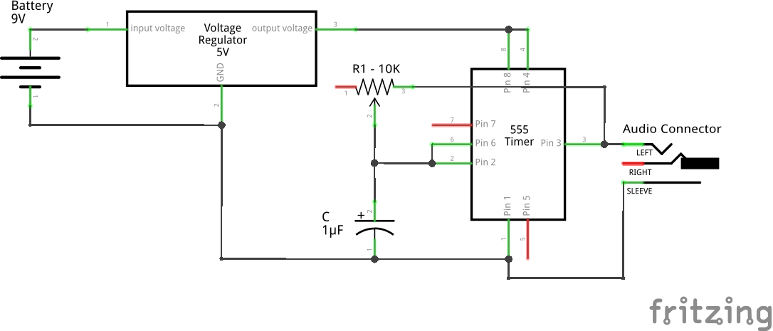
Trivial Square Wave using 555 (Schematic)
Note that, both the charging & discharging paths would have the same resistor R & capacitor C. So, putting in the equations (1) & (2) derived in the previous article, we would get,
")
thus giving a 50% duty cycle.
Live Demo
Excited by his idea, Pugs couldn’t wait but try out the same. So, he set the above circuitry on a breadboard as shown in the figure below:
WARNING: Do NOT put the pot to a value of zero, as that will overload the circuit. A safety workaround could be to put a fixed 1K resistor in series with the pot.
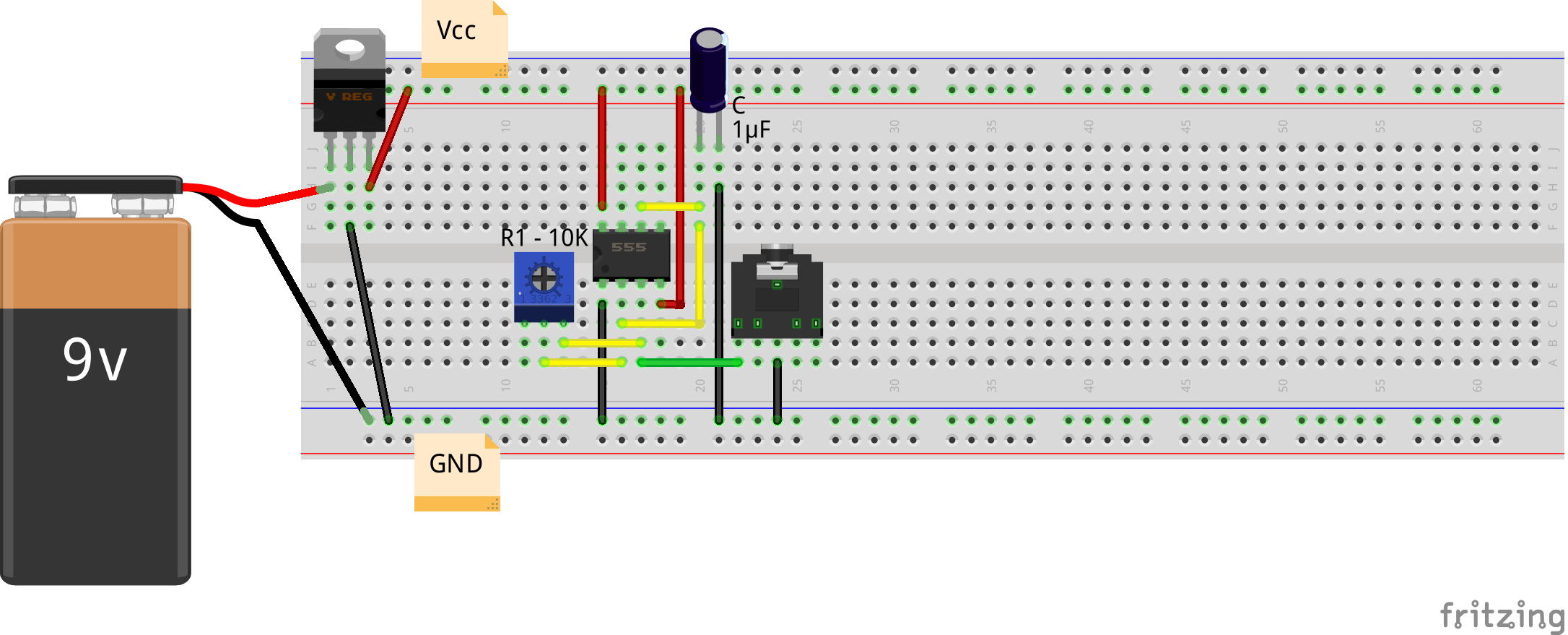
Trivial Square Wave using 555 (Breadboard)
The audio jack is being used for observing the waveforms on the home-made PC oscilloscope, as created in his previous PC Oscilloscope article.
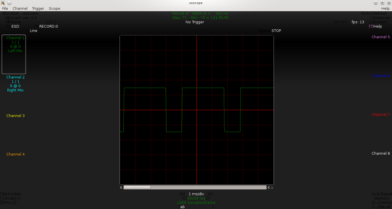
Then, for C as a 1μF capacitor, he adjusted R to different values to get different frequencies with 50% duty cycle. But, what’s this, none of them have a 50% duty cycle.
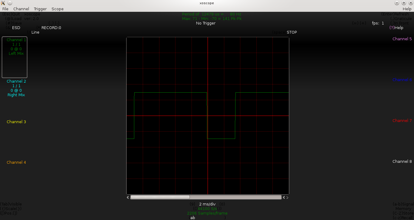
Below are some of the waveforms being observed by Pugs, for the values of R being adjusted to 1.5KΩ, 5KΩ, 10KΩ:
R = 1.5K
R = 5K
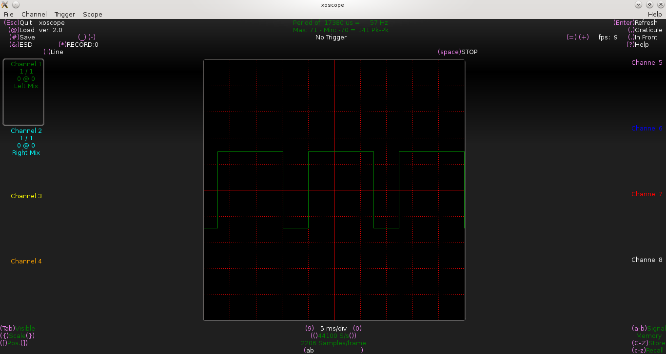
R = 7K
From the above waveforms, we approximately have the following t_on & t_off:
R = 1.5KΩ => t_on = 2.8ms, t_off = 1.1ms
R = 5KΩ => t_on = 8.9ms, t_off = 3.4ms
R = 7KΩ => t_on = 12.5ms, t_off = 4.8ms
Now, as per equation (3), for C = 1μF, and the above three R values, we should have got the following:
R = 1.5KΩ => t_on = t_off = 1.0ms
R = 5KΩ => t_on = t_off = 3.5ms
R = 7KΩ => t_on = t_off = 4.9ms
t_offs are pretty exact, but t_ons are really high. After quite a bit of analysis, Pugs realized that the peak Vo is not actually reaching Vcc. Debugging trick he used, was to replace the 1μF capacitor by a 100μF capacitor, thus reducing the frequency in Hz (eye observable), and then measuring the Vo using a multimeter. Aha! if the Vo doesn’t reach Vcc, then in the above circuit, we are not charging the capacitor using Vcc but this measured peak value of Vo. Mathematically, this changes our derivation for equation (1) in the previous article, though equation (2) remains the same. And hence, getting a correct t_off but incorrect t_on. Even conceptually, we can see that as Vo is less than Vcc, the capacitor would take more time to charge, and thus increasing the time (t_on), as observed in all the readings above.
On this realization, Pugs approximated the measured value of maximum Vo to 3.65V, i.e. 3.65/5 of Vcc instead of Vcc in deriving the equation (1) of the previous article, getting the following relation:
 + 1/3 * V_{cc} * e^{\frac{-t_{on}}{R*C}}")
which on simplifying gives:
 = R * C * 1.8347")
Putting in the values, gave t_on values amazingly close to the observed values, thus again verifying the theory.
Summary
Also from the 555 IC datasheet, Pugs found that there is always some expected drop on the peak Vo from the supply voltage Vcc, and the peak Vo in most cases would be less than Vcc – thus rendering all our standard calculations of t_on futile. In fact, if we put the actual value of peak Vo in our calculations, we would get the results as observed. But getting the actual value of Vo is non-trivial and non-standard. Moreover, even if we do that somehow, we are not going to get our desired 50% duty cycle.
Thus, moral of the story is that, in general, Vo should not be used to generate the trigger voltages, as practically it may not be reaching Vcc, as in the case above. And, Pugs would have to find out some other way to achieve 50% duty cycle.
The author is a hobbyist in open source hardware and software, with a passion for mathematics, and philosopher in thoughts. A gold medallist from the Indian Institute of Science, Linux, mathematics and knowledge sharing are few of his passions. He experiments with Linux and embedded systems to share his learnings through his weekend workshops. Learn more about him and his experiments at https://sysplay.in.


Pingback: Square Wave using 555 | Playing with Systems
Pingback: Symmetric Square Wave using 555 | Playing with Systems