Water Level Indicator

This 4th article in the series of “Do It Yourself: Electronics”, takes you through using a bipolar junction transistor (BJT), as an electronic switch.

<< Previous Article

Pugs came out of the “Electronics Fundamentals” class, all loaded with internal details of a transistor. He was lost in his own world, when he crossed ways with Surya coming out of his class. Surya called Pugs, without any response. So, he came close and shook Pugs, “Hey Pugs! Where are you?”

Pugs, as if he woke up from deep sleep, “Hey! What happened? Where are you going?”

“Where were you lost? Whom were you remembering? Shall I call Simi?”

“Hey! Shut up yaar. Where did she come in between? I was thinking of how to use the transistors in a practical way”, replied Pugs showing anger.

“Okay. Okay. Cool down. I was just joking. So, today your class was about transistors.”

“Yes.”

“Last time when you went to buy some components, I asked you to get four BC546 transistors, right?”

“Yes. I got them.”

“So now, I think is the time to experiment with them, to bring you back from the lost world.”

“O Great! But you know what, if I remember correct, the shopkeeper didn’t have BC546, and so he gave some other number, saying that is equivalent.”

“Which number?”

“Not really sure.”

“No probs. Let’s go to your room and check it out.”

Both Surya and Pugs walks down to Pugs’ room.

Pugs took out the transistors, trying to check the number written on them.

“Looks like BC548. Can you check, Surya?”

“Yes it is BC548. That’s fine. In fact, BC546 & BC547 are same as BC548, except that they have higher break down voltages. Moreover, there are other variants as well, like BC549 – a low noise variant, BC550 – with both low noise and higher break down voltage.”

“I don’t understand your all these Greek-Latin – just tell me if what I got is okay.”

“Ya ya that’s fine. It is also NPN like the others.”

“Yes, that I understand – meaning there is a very thin layer with concentrated holes sandwiched between two layers with concentrated electrons, and so the electrons are the majority carriers in these kinds.”

“O! That’s great – you know quite a bit about them. Hmmm! I see the effect of the class”, said Surya staring at Pugs.

Interrupting Surya’s stare, Pugs said, “Ignore that, and tell me then, do we also have similar PNP transistors?”

“Yes. There is a similar series BC556 to BC560 for PNP transistors.”

“Hmmm! So now, what are we planning to do with these four BC548’s.”

“Use them as electronic switches for water level indication.”

And then goes the demonstration by Surya:

“Hey Surya! You have put the power line into the water. Isn’t that dangerous?”

“It is just 5 volts, Pugs. And more than that the current would be in micro amps, as it is the input to the base of the transistors.”

“I see. And that can be ignored – too small to observe in this noisy world.”

“With water, yes. However, with hazardous liquids like petrol, even that may not be okay.”

Next Article >>

   Send article as PDF   

Kernel Threads

<< Previous Article

In the previous article, we learned to write a simple kernel module. This was needed to kick start our journey into the Kernel Internals, as all of the code we are going to discuss, has to be pushed into the kernel as module. In this article, we will discuss about the Kernel Threads. So, lets begin…

Understanding Threads

Threads, also known as light weight processes are the basic unit of CPU initialization. So, why do we call them as light weight processes? One of the reason is that the context switch between the threads takes much lesser time as compared to processes, which results from the fact that all the threads within the process share the same address space, so you don’t need to switch the address space. In the user space, threads are created using the POSIX APIs and are known as pthreads. Some of the advantages of the thread, is that since all the threads within the processes share the same address space, the communication between the threads is far easier and less time consuming as compared to processes. And usually is done through the global variables. This approach has one disadvantage though. It leads to several concurrency issues and require the synchronization mechanisms to handle the same.

Having said that, why do we require threads? Need for the multiple threads arises, when we need to achieve the parallelism within the process. To give you the simple example, while working on the word processor, if we enable the spell and grammar check, as we key in the words, you will see red/green lines appear, if we type something syntactically/grammatically incorrect. This can most probably be implemented as threads.

Kernel Threads

Now, what are kernel threads? They are same as user space threads in many aspects, but one of the biggest difference is that they exist in the kernel space and execute in a privileged mode and have full access to the kernel data structures. These are basically used to implement background tasks inside the kernel. The task can be handling of asynchronous events or waiting for an event to occur. Device drivers utilize the services of kernel threads to handle such tasks. For example, the ksoftirqd/0 thread is used to implement the Soft IRQs in kernel. The khubd kernel thread monitors the usb hubs and helps in configuring  usb devices during hot-plugging.

APIs for creating the Kernel thread

Below is the API for creating the thread:

#include <kthread.h>
kthread_create(int (*function)(void *data), void *data, const char name[], ...)

Parameters:
function – The function that the thread has to execute
data – The ‘data’ to be passed to the function
name – The name by which the process will be recognized in the kernel

Retuns: Pointer to a structure of type task_struct

Below is an example code which creates a kernel thread:

#include <linux/module.h>
#include <linux/kernel.h>
#include <linux/delay.h>

static struct task_struct *thread_st;
// Function executed by kernel thread
static int thread_fn(void *unused)
{
    while (1)
    {
        printk(KERN_INFO "Thread Running\n");
        ssleep(5);
    }
    printk(KERN_INFO "Thread Stopping\n");
    do_exit(0);
    return 0;
}
// Module Initialization
static int __init init_thread(void)
{
    printk(KERN_INFO "Creating Thread\n");
    //Create the kernel thread with name 'mythread'
    thread_st = kthread_create(thread_fn, NULL, "mythread");
    if (thread_st)
        printk("Thread Created successfully\n");
    else
        printk(KERN_INFO "Thread creation failed\n");
    return 0;
}
// Module Exit
static void __exit cleanup_thread(void)
{
    printk("Cleaning Up\n");
}

In the above code, thread is created in the init_thread(). Created thread executes the function thread_fn(). Compile the above code and insert the module with insmod. Below is the output, you get:

Thread Created successfully

That’s all we get as an output. Now, you might be wondering why is thread_fn() not executing? The reason for this is, when we create the thread with kthread_create(), it creates the thread in sleep state and thus nothing is executed. So, how do we wake up the thread. We have a API wake_up_process() for this. Below is modified code which uses this API.

// Module Initialization
static struct task_struct *thread_st;
{
    printk(KERN_INFO "Creating Thread\n");
    //Create the kernel thread with name 'mythread'
    thread_st = kthread_create(thread_fn, NULL, "mythread");
    if (thread_st)
    {
        printk("Thread Created successfully\n");
        wake_up_process(thread_st);
    }
    else
        printk(KERN_INFO "Thread creation failed\n");
    return 0;
}

As you might notice, wake_up_process() takes pointer to task_struct as an argument, which in turn is returned from kthread_create(). Below is the output:

Thread Created successfully
Thread Running
Thread Running
...

As seen, running a thread is a two step process – First create a thread and wake it up using wake_up_process(). However, kernel provides an API, which performs both these steps in one go as shown below:

#include <kthread.h>
kthread_run(int (*function)(void *data), void *data, const char name[], ...)

Parameters:
function – The function that the thread has to execute
data – The ‘data’ to be passed to the function
name – The name by which the process will be recognized in the kernel

Returns: Pointer to a structure of type task_struct

So, just replace the kthread_create() and wake_up_process() calls in above code with kthread_run and you will notice that thread starts running immediately.

Conclusion

So, now we are comfortable with creating the threads, let us remove the module with rmmod.  What do you get? Oops…isn’t it? To understand the reason for the crash, stay tuned to my next article on kernel threads. Till then, good bye.

Next Article >>

   Send article as PDF   

Sensing Someone Around

This 3rd article in the series of “Do It Yourself: Electronics”, takes you through the basics of infra red sensing using an IR LED and an IR diode.

<< Previous Article

Early morning, Pugs went to the ECE Department to meet Surya, who was creating some experiments for his juniors.

“What are you doing at this time in your department lab?”, exclaimed Pugs to Surya.

“Setting up a robot framework for our ECE juniors, for the robotic showcase planned for today afternoon”, replied Surya

“Interesting. I see that you are also using the IR transmitter and the IR receiver, you asked me to buy. By the name itself, I can make out that one would transmit IR signals, and other would receive the same. But what could we use them for?”

“These can be used for a wide range of applications …”

“To me it seems like another light sensor. Sun also emits IR. So, may be we can detect presence of sun”, interrupted Pugs.

“Why only sun? Even our bodies are good source of IR”, added Surya.

“Okay. So, do we detect sunlight, living beings, etc using the IR receiver? But then what is the IR transmitter for?”

“We can detect, but for that we may need more sophistication to eliminate the unwanted IRs. Anyways, the purpose here is not that. It is more of obstacle detection, and that’s where, we need this IR transmitter, as well.”

“I see. So, how do these IR Tx & Rx pair work?”

“Let me just show you a small working demo of the same.”

With that Surya picked up the various stuff needed, from around the lab, and showed the following:

Pugs went to his room & rebuilt the circuit. But to his surprise, the LED was always on. He tried debugging it, as in his previous light sensing circuit, but in vain. So, in frustration, he called up Surya and said, “Surya, your debugging gyaan is not working out. I tried all your suggested debugging tricks, but not able to figure out the problem in my circuit”.

“What happened? Have you powered up your circuit?”, queried Surya.

“Yes obviously. And that’s what the problem is. In my circuit, the LED is now always powered on”, replied Pugs with a sarcastic voice.

“Where have you put the circuit?”, asked Surya.

“On my table. Where else?”

“Put it below the table, and check out.”

“Why are you joking with me? How does it matter, whether I put it above or below the table?”

“Just try it, na”, emphasized Surya.

So, unwillingly Pugs put his circuit below the table, and viola the LED went off. And then, when he hovered his hand over the circuit, the LED switched on. He couldn’t believe himself. So, he tried the same multiple times. Then, he also put back the circuit on the table to check the problem, again. And yes, it was there. But all fine, when below the table.

“What happened Pugs? Did it work?”, asked Surya, as he didn’t receive any response from Pugs for a while.

“Yaaa. It is working. But how?”

“Now as it is working, I can explain you. Remember, you only told me that sun also emits IR, and your table is near the window. So, the IR receiver was always getting the IR, and hence LED was always on.”

“A ha! That’s cool. So, when I put it below the table – no IR from the sun – and things worked. That’s a great insight, that when we are playing with real world stuff, we need to keep our minds and thoughts open to all possibilities.”

“In fact, there is a simpler way to fix this problem. But I thought, why not have this fun experience.”

“What’s that?”, asked Pugs curiously.

“You may just adjust the pot to appropriately set the threshold value, depending on where you are keeping your circuit.”

“O ya! That’s what we have put the pot for.”

Next Article >>

   Send article as PDF   

Linux Kernel Module

<< Previous Article

In Linux kernel, drivers can be put in two ways. One is, you make it as a part of kernel and will be part of vmlinux image. Another thing is to build the drivers separately and dynamically plug it into the Kernel. So, the driver which is loaded dynamically into the kernel is known as kernel module. Modules are very handy during the development phase.

Writing a Simple Kernel Module

Before writing a module, you need to understand the kernel C. So, you might be wondering, do I need learn one more language for coding in Kernel? Don’t worry, Kernel C is normal pure C with GNU extensions. Now, what is pure C? It means C without access to any user space libraries such as glibc. Kernel includes all the code as a part of itself. This is the code which kernel developers have developed as a part of kernel and is placed at <kernel_source>/kernel/lib.

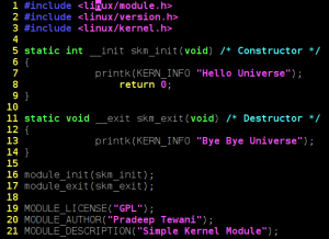
One of the beautiful thing about the kernel is that, though its written in C, but it follows the object oriented concepts. This is evident from the very first module which we will try. Below is the simple kernel module:

Simple Kernel Module

Figure 1: Simple Kernel Module

As can be seen, every module has a constructor and destruction function. skm_init is the constructor and skm_exit is the destructor. Now, as with object oriented programming, constructor is invoked when the the object is instantiated, similarly, over here, constructor is invoked when the module is dynamically loaded into the kernel. So, when will destructor be invoked? Of course, when the module is plugged out of the kernel. Macros module_init() and module_exit() are used to specify the constructor and destructor for a module.

Equivalent of printf() in kernel is printk().

Header file ‘kernel.h’ is kernel space header file which includes the prototype for printk and other commonly used functions. module.h includes the module related data structures and APIs. Macros module_init() and module_exit() are defined here. File version.h contains the kernel version. This is included for the module version to be compatible with kernel into which the module will be loaded.

Apart from this, we have a macros beginning with MODULE_. These specify the module related information and form the module’s signature.

Building a Kernel Module

In order to build a kernel module, you need to have the kernel source code which is usually found at /usr/src/linux. If not kernel source, at least you need the kernel headers. Building a kernel module is different from a building any application. Normally, applications are compiled using the gcc command and by default, gcc picks up the libraries in /usr/lib. But, as discussed earlier, kernel code is a self-contained and doesn’t uses the libraries from the user space. So, we need to give the command line options to gcc to not to take the standard libraries. Not only that, since the module is going to be the hot plugged into the kernel, it has to be compiled with the same flags as the kernel was compiled with. In order to take care of these things, we invoke the kernel makefile to compile our module.

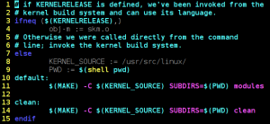
Below is the makefile for compiling the module:

Figure 2: Makefile For Kernel Module

Here, it is assumed that the kernel source is placed at /usr/src/linux/. If it is placed at any other location, update the location in KERNEL_SOURCE variable in this Makefile.

To build the module, invoke make as below:

$ make

The output of the make would be skm.ko.

Dynamically Loading/Unloading a Kernel Module

We use insmod command to load the kernel module as below. We need to execute this command with root privileges

$ insmod skm.ko

In order to list the modules, execute lsmod as below. This will show you the skm loaded.

$ lsmod

And for removing/unloading the module, execute rmmod command as below:

$ rmmod skm

Note that while unloading, we use module name (skm), not the file name (skm.ko).

Conclusion

So, now we are comfortable with writing & building a kernel module. This is the basic building block of the Linux kernel development. In the following articles, we will dive into the Linux Kernel Programming. So, stay tuned!

Next Article >>

   Send article as PDF   

Sensing the Light Around

This 2nd article in the series of “Do It Yourself: Electronics”, starts with the journey of sensors.

<< Previous Article

After attending their regular afternoon classes, Surya & Pugs met near the Innovation Centre, headed towards their hostel rooms.

“What a waste of energy!”, exclaimed Surya pointing out to the street lights glowing on in the bright day.

“Possibly the switch man is not well and couldn’t come to switch off the lights”, said Pugs calming Surya.

“But, why do you need a switch man for switching on and off street lights?”, retorted Surya.

“What do you mean?”, asked Pugs with a puzzled look.

“These could be made automatic – what else?”

“Switch man may be more cost-effective than automating all these street lights.”

“I don’t think so – given that it can be achieved by simple & cheap electronic circuitry.”

“O Really! Then, why don’t we make and give it to the college? And, I can learn a new circuit.”

“Not a bad idea. Let us then first make a working sample.”

With that Pugs followed Surya into his room to watch the design evolve.

“By the way, what kind of circuit would it be?”, asked Pugs curiously.

“Think and you tell me. That is the first part of the design”, replied Surya.

Pugs contemplated a while and said “Something which switches off when sunlight is there.”

“Not bad. In fact, it should also switch on when light is less. And, that’s a light sensing circuit.”

“But how do we sense light electronically?”

“Why only light? A whole lot of stuff around us can be sensed using components called sensors. They come in whole variety, converting one form of energy into an another. And in electronics, we would like to use those that some how translates the energy into voltage. We have light sensors, sound sensors, humidity sensors, … – you name it.”

“Wow! So, then we can automate all kind of things.”

“Yes. That’s the power & beauty of sensors.”

With that, Surya takes out the light dependent resistor (LDR) and various other components needed for designing the light sensing circuit. And, here is how he demonstrated the complete design and working to Pugs:

As soon as Surya was done, Pugs quipped “That was simple. Even I can do it, now.”

“Exactly, that’s what I was telling you”, boosted Surya, dismantling the so built breadboard design.

“Hey, why are you breaking it?”, asked Pugs trying to stop Surya.

“That was simple. And so now you design it”, replied Surya challenging Pugs to redo the design on his own.

Pugs took up the challenge, and started building the circuit. He used the following two pointers from the notes taken by him during Surya’s demo:

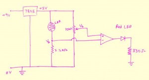
LDR Circuit

LDR Circuit

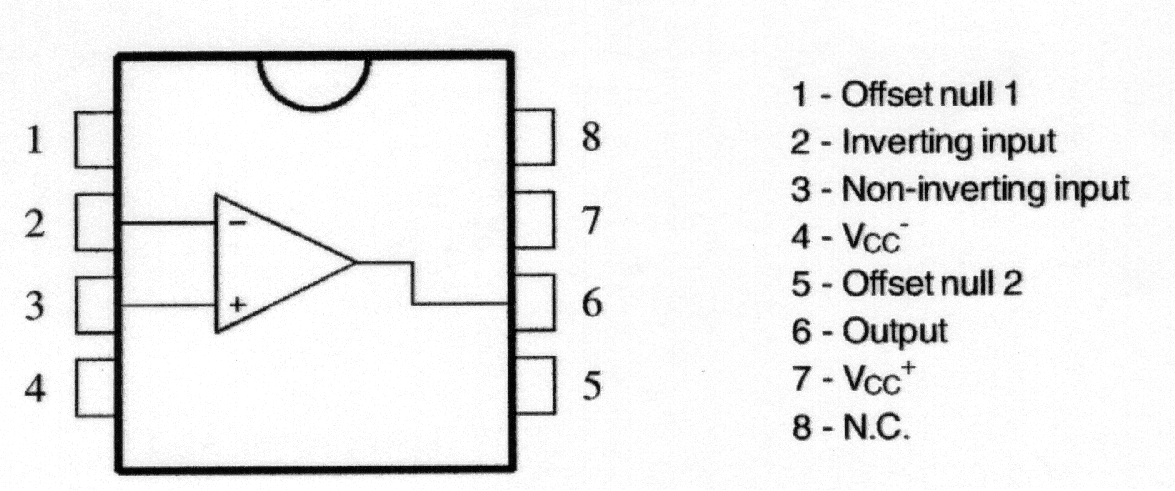
741 OpAmp Pinout

741 OpAmp Pinout

He took some time but was able to build a similar circuit. However, to his surprise, it was not working. He tried tightening the ICs, shaking the wires – but no luck. Not wanting to give up his first circuit design challenge, he said “Hey Surya, I feel that circuit connections are okay, but something else is wrong. In programming, if we are not getting output, we can debug our program by putting prints. Is there something like that, I can do here as well?”

Surya gave a naughty smile understanding Pugs’ intention of not giving up, and poked “So, do you want me to debug it for you?”

“No-no. You just tell me the techniques of debugging. I’ll do it myself”, retorted Pugs.

“Okay then. Let me give you a quick debugging demo of possibilities” – and here’s what Surya showed to Pugs:

With that, Pugs was literally able to debug his circuit, and get the LED switch on when light is there and switch off when light is covered. “Aha! that’s not quite right. The logic is inverted”, exclaimed Pugs. At this, Surya couldn’t control himself, and quipped, “Yes. That’s because you have swapped the -ve and +ve connections of the Opamp.”

With that, Pugs reversed the connections and viola – everything was working right.

Super excited with the light sensing gyan from Surya, Pugs went to the local market to purchase the various components to build his own circuits. He purchased all the stuff shown to him by Surya till now, and then called up Surya asking what else shall he purchase, may be for his next circuit experiment. Surya suggested him to get an infra red transmit LED, an infra red receive diode, and four BC546 transistors.

Next Article >>

   Send article as PDF   

Introduction to Linux Kernel

What is Kernel?

Looking at the dictionary, the meaning of the kernel is core. But, as we know kernel refers to the operating system. So, what is kernel core of? In fact, kernel is the core of the overall system. Kernel is the system manager. It manages the system resources. So, what all are resources, we have in the system? This is explained as below:

CPU: This is one of the important resource, we have in system. It is the brain of the system. So, it is very important to optimally use this resource. Now, the question comes, how to manage the CPU. One of the mechanism to optimally use the CPU is, what we call as multitasking. Literal meaning of multitasking is doing more than one thing at a time. But, actually speaking, since in the uniprocessor system, we have a single CPU, so at a time, we execute only program, but to get the feeling of multi-tasking, kernel switches among the processes and switching happens to be so fast that, it seems like processor is executing all the processes at once. The subsystem in kernel which enables to achieve this multi-tasking is called scheduler. The task of managing the CPU is what we call as Process Management or Process Scheduling.

Memory: Another important resource, which we have in the system is the memory. When I say memory, it refers to the RAM. Since all the processes require the memory to execute, memory has to be shared among the processes in such a way that one process should not interfere with another process’ memory. Also, there is concept of virtual addressing, which gives the illusion of having more memory than the available RAM. So, subsystem of the kernel which does this task is memory manager. This task of managing the memory is known as Memory Management.

Input/Output (I/O): As you understand, system has various IO devices such as keyboard, mice, and speakers and so on. The task of managing the IO’s is what we call as IO Management.

Storage: This resource is used for storing the data in the non-volatile memory such as hard-disk. We usually store the data in form of files. So the subsystem in the kernel which deals with creation/deletion and management of files is Filesystem. This task of the kernel is what we call as Storage Management.

Network: In order to communication across the systems, we require the network. So, what needs to be managed in the network? There is networking protocol stack and the network interface card (NIC). The task of managing the network is what we call as Network Management.

So, to summarize, kernel performs the five main tasks – Process Management, Memory Management, I/O Management, Storage Management and Network Management.

Linux Kernel Source Organization

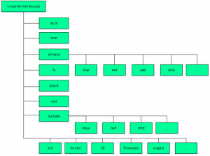
As you might be aware, Linux was developed by Linus Torvalds as an academic project. So, he started to create the directory for each functionality. Figure 1 below shows the kernel source code organization at a higher level.


kernel_source

 Figure 1: Linux Kernel Source Organization

As seen, there are directories corresponding to all the five functionality. Process management includes two things, one is the processor related code and the other is scheduling. So, all the CPU related code falls in the arch directory. It contains the directories for various processors. And, for scheduling, there are files starting with sched in directory kernel. For memory management, there is a directory called ‘mm’. So, all the code for managing the memory among the processes, shared memory, managing the mallocs, lies over here. Similarly, for most of the Input/Output management, there is folder called drivers. For storage management, there is directory called fs. It contains the code for various filesystem logic such as Ext2, Ext3, Fat32 and so on. For network, there is a directory called net which contains the code for protocols stack and in the drivers, there is a directory called net for interfacing with network interface card.

Apart from this, there are kernel and lib directories, which contain the architecture independent code in kernel. Similarly, linux directory, under include, contains the headers for architecture independent code in kernel. init contains the code which is used during the kernel boot-up.

Next Article >>

   Send article as PDF   

Building Circuits from Scratch

This is all about “Do It Yourself: Electronics”, as how it started between two college friends from NIT Warangal.

“Oh! It was a total tangential lecture today”, sighed Pugs in the cafeteria.

“Why? What happened Pugs? What was it about?”, asked Surya.

“Electronics Fundamentals, yaar”, replied Pugs.

“But, why in this world have you chosen that elective, you being a comps guy?”, asked Surya with curiosity.

“I wish to design some electronic circuits of my own. So thought, that might be helpful.”

“That sounds interesting. But I can understand, what would you have felt in the lecture. BTW, what was the topic today?”

“Don’t ask me yaar. All these electrons moving around, then these imaginary holes, the potential barriers, and what not. After initial 5 minutes, I was totally lost.”

“You know what? You don’t really need to know all these gory details to design basic electronic circuits. And moreover, you should go by the top-down approach to fulfill your wish.”

“O really! And what is this top-down approach”, exclaimed Pugs.

“What I mean is that you should first start playing with the various electronics components, understand their practical usages by designing simple breadboard circuits. And, then go into the gory details, if necessary”, explained Surya.

“That’s wonderful. Design the circuits first. Cool!! … But how do I start? I don’t have any clue about what components, etc”

“That’s easy. I can give you a practical hands-on kick-starter.”

“That’s great Surya. I hope after that I’d be able to start designing circuits, and may be able to make sense out of the lectures, as well.”

“Ya sure Pugs. Let’s go to my room. I have various electronics stuff there to get you started.”

“Just an idea. I know, I am going to get an amazing kick-starter, and there may be many more like me. So, why not record your kick-starter.”

“Hey! No yaar. It is just for you”, Surya replied shyly, thinking of the public exposure.

“Come on Surya. Think of it. Your knowledge sharing could benefit so many.”

“Hmmm!! …”

“Don’t think so much. I know that would thrill you. Let me get the photography club guys to film it.”

All set in Surya’s room, he took out his various electronics stuff, and started explaining them to Pugs, as follows:

Pugs was all excited after this first level of kick-starter by Surya, and requested Surya to show the video on resistor colour coding, as well.

Here is what Surya showed on his laptop:

“I understood what all you showed me. But how do I use the various things?”, queried Pugs. “Okay. So, I’ll now show you the simplest electronics circuit – ‘Blinking an LED'”, replied Surya. And, here is what he did:

“That was really simple. Something like the ‘Hello World’ program we write, when we start learning a programming language”, expressed Pugs. “Exactly, that’s what it is in the electronics world – blinking an LED”, confirmed Surya.

“Chalo Pugs, let’s go for lunch”, said Surya, trying to shutdown his laptop. Pugs interrupted, “Ay no Surya. Just before we go for lunch, I have a small doubt”. “Ya, tell me”, asked Surya. “Theoretically, you explained to me about the various current, voltage, resistor values from the datasheets etc, and then built the circuit. Do this circuit, really have those values?”, doubted Pugs. “What do you think?” asked Surya. “If you are asking means should be, otherwise how would the circuit work.”, Pugs tried to confirm with Surya. “Yes and No. They would be close to those values but not exact – and that is what is practical about it – to be tolerant about the tolerances. To drive the point home, I think, let me show you the actual readings using a Digital MultiMeter (DMM)”. And with that, Surya demonstrated the following measurements:

Next Article >>

   Send article as PDF   

The Semester Project – Part VII: File System in Action

This twenty-fourth article, which is part of the series on Linux device drivers, gets the complete real SIMULA file system module in action, with a real hardware partition on your pen drive.

<< Twenty-third Article

Real SFS in action

Code available from rsfs_in_action_code.tbz2 gets to the final tested implementation of the final semester project of Pugs & Shweta. This contains the following:

  • real_sfs.c – contains the code of earlier real_sfs_minimal.c plus the remaining real SIMULA file system functionalities. Note the file system’s name change from sfs to real_sfs
  • real_sfs_ops.c & real_sfs_ops.h – contains the earlier code plus the additional operations needed for the enhanced real_sfs.c implementations
  • real_sfs_ds.h (almost same file as in the previous article, plus a spin lock added into the real SFS info structure to be used for preventing race conditions in accessing the used_blocks array in the same structure)
  • format_real_sfs.c (same file as in the previous articles) – the real SFS formatter application
  • Makefile – contains the rules for building the driver real_sfs_final.ko using the real_sfs_*.* files, and the format_real_sfs application using the format_real_sfs.c

With all these and earlier details, Shweta completed their project documentation. And so finally, Shweta & Pugs were all set for their final semester project demo, presentation and viva.

The highlights of their demo (on root shell) are as follows:

  • Loading real_sfs_final driver: insmod real_sfs_final.ko
  • Using the previously formatted pen drive partition /dev/sdb1 or Re-formatting it using the format_real_sfs application: ./format_real_sfs /dev/sdb1. Caution: Please check out the complete detailed steps on this from the previous article, before you actually format it
  • Mount the real SFS formatted partition: mount -t real_sfs /dev/sdb1 /mnt
  • And … And what? Browse the mounting filesystem. Use your usual shell commands to operate on the file system: ls, cd, touch, vi, rm, chmod, …

Figure 40 shows the real SIMULA file system in action

Figure 40: The real SIMULA file system module in action

Figure 40: The real SIMULA file system module in action

Realities behind the action

And if you really want to know, what are the additional enhancements Pugs added to the previous article’s code to get to this level, it is basically the following core system calls as part of the remaining 4 out of 5 set of structures of function pointers (in real_sfs.c):

  1. write_inode (under struct super_operations) – sfs_write_inode() basically gets a pointer to an inode in the VFS’ inode cache, and is expected to sync that with the inode in physical hardware space file system. That is achieved by calling the appropriately modified sfs_update() (defined in real_sfs_ops.c) (adapted from the earlier browse_real_sfs application). The key parameter changes being passing the inode number instead of the filename and the actual timestamp instead of the flag for its update status. And accordingly, the call to filename based sfs_lookup() is being replaced by inode number based sfs_get_file_entry() (defined in real_sfs_ops.c), and additionally now the data blocks are also being freed (using sfs_put_data_block() (defined in real_sfs_ops.c)), if the file size has reduced. Note that sfs_put_data_block() (defined in real_sfs_ops.c) is a transformation of the put_data_block() from the browse_real_sfs application. Also, note the interesting mapping to / from the VFS inode number from / to our zero-based file entry indices, using the macros S2V_INODE_NUM() / V2S_INODE_NUM() in real_sfs_ops.h.
    And finally, underlying write is being achieved using write_to_real_sfs(), a function added in real_sfs_ops.c, very similar to read_from_real_sfs() (already there in real_sfs_ops.c), except the direction reversal of the data transfer and marking the buffer dirty to be synced up with the physical content. Alongwith, in real_sfs_ops.c, two wrapper functions read_entry_from_real_sfs() (using read_from_real_sfs()) and write_entry_to_real_sfs() (using write_to_real_sfs()) have been written and used respectively for the specific requirements of reading and writing the file entries, to increase the code readability. sfs_write_inode() and sfs_update() are shown in the code snippet below. sfs_write_inode() has been written in the file real_sfs.c. For others, check out the file real_sfs_ops.c
#if (LINUX_VERSION_CODE < KERNEL_VERSION(2,6,34))
static int sfs_write_inode(struct inode *inode, int do_sync)
#else
static int sfs_write_inode(struct inode *inode, struct writeback_control *wbc)
#endif
{
	sfs_info_t *info = (sfs_info_t *)(inode->i_sb->s_fs_info);
	int size, timestamp, perms;

	printk(KERN_INFO "sfs: sfs_write_inode (i_ino = %ld)\n", inode->i_ino);

	if (!(S_ISREG(inode->i_mode))) // Real SFS deals only with regular files
		return 0;

	size = i_size_read(inode);
	timestamp = inode->i_mtime.tv_sec > inode->i_ctime.tv_sec ?
			inode->i_mtime.tv_sec : inode->i_ctime.tv_sec;
	perms = 0;
	perms |= (inode->i_mode & (S_IRUSR | S_IRGRP | S_IROTH)) ? 4 : 0;
	perms |= (inode->i_mode & (S_IWUSR | S_IWGRP | S_IWOTH)) ? 2 : 0;
	perms |= (inode->i_mode & (S_IXUSR | S_IXGRP | S_IXOTH)) ? 1 : 0;

	printk(KERN_INFO "sfs: sfs_write_inode with %d bytes @ %d secs w/ %o\n",
		size, timestamp, perms);

	return sfs_update(info, inode->i_ino, &size, &timestamp, &perms);
}

int sfs_update(sfs_info_t *info, int vfs_ino, int *size, int *timestamp, int *perms)
{
	sfs_file_entry_t fe; 
	int i;
	int retval;

	if ((retval = sfs_get_file_entry(info, vfs_ino, &fe)) < 0) 
	{   
		return retval; 
	}   
	if (size) fe.size = *size;
	if (timestamp) fe.timestamp = *timestamp;
	if (perms && (*perms <= 07)) fe.perms = *perms;

	for (i = (fe.size + info->sb.block_size - 1) / info->sb.block_size;
		i < SIMULA_FS_DATA_BLOCK_CNT; i++)
	{   
		if (fe.blocks[i])
		{   
			sfs_put_data_block(info, fe.blocks[i]);
			fe.blocks[i] = 0;
		}   
	}   

	return write_entry_to_real_sfs(info, V2S_INODE_NUM(vfs_ino), &fe);
}
  1. create, unlink, lookup (under struct inode_operations) – All the 3 functions sfs_inode_create(), sfs_inode_unlink(), sfs_inode_lookup() have the 2 common parameters (the parent’s inode pointer and the pointer to the directory entry for the file in consideration), and these respectively create, delete, and lookup an inode corresponding to their directory entry pointed by their parameter, say dentry.
    sfs_inode_lookup() basically searches for the existence of the filename underneath using the appropriately modified sfs_lookup() (defined in real_sfs_ops.c) (adapted from the earlier browse_real_sfs application – the adoption being replacing the user space lseek()+read() combo by the read_entry_from_real_sfs()). If filename is not found, then it invokes the generic kernel function d_splice_alias() to create a new inode entry in the underlying file system, for the same, and then attaches it to the directory entry pointed by dentry. Otherwise, it just attaches the inode from VFS’ inode cache (using generic kernel function d_add()). This inode, if obtained fresh (I_NEW), needs to be filled in with the real SFS looked up file attributes. In all the above implementations and in those to come, a few basic assumptions have been made, namely:

    • Real SFS maintains mode only for user and that is mapped to all 3 of user, group, other of the VFS inode
    • Real SFS maintains only one timestamp and that is mapped to all 3 of created, modified, accessed times of the VFS inode.

    sfs_inode_create() and sfs_inode_unlink() correspondingly invokes the transformed sfs_create() and sfs_remove() (defined in real_sfs_ops.c) (adapted from the earlier browse_real_sfs application), for respectively creating and clearing the inode entries at the underlying hardware space file system, apart from the usual inode cache operations, using new_inode()+insert_inode_locked(), d_instantiate() & inode_dec_link_count(), instead of the earlier learnt iget_locked(), d_add(). Apart from the permissions and file entry parameters, and replacing lseek()+read() combo by read_entry_from_real_sfs(), sfs_create() has an interesting transformation from user space to kernel space: time(NULL) to get_seconds(). And in both of sfs_create() and sfs_remove() the user space lseek()+write() combo has been replaced by the obvious write_entry_to_real_sfs(). Check out all the above mentioned code pieces in the files real_sfs.c and real_sfs_ops.c, as mentioned.

  2. readpage, write_begin, writepage, write_end (under struct address_space_operations) – All these address space operations are basically to read and write blocks on the underlying filesystem, and are achieved using the respective generic kernel functions mpage_readpage(), block_write_begin(), block_write_full_page(), generic_write_end(). First one is prototyped in <linux/mpage.h> and remaining 3 in <linux/buffer_head.h>. Now, though these functions are generic enough, a little thought would show that the first three of these would ultimately have to do a real SFS specific transaction with the underlying block device (the hardware partition), using the corresponding block layer APIs. And that exactly is achieved by the real SFS specific function sfs_get_block(), which is being passed into and used by the first three functions, mentioned above.
    sfs_get_block() (defined in real_sfs.c) is invoked to read a particular block number (iblock) of a file (denoted by an inode), into a buffer head (bh_result), optionally fetching (allocating) a new block. So for that, the block array of corresponding real SFS inode is looked up into and then the corresponding block of the physical partition is fetched using the kernel API map_bh(). Again note that to fetch a new block, we invoke the sfs_get_data_block() (defined in real_sfs_ops.c), which is again a transformation of the get_data_block() from the browse_real_sfs application. Also, in case of a new block allocation, the real SFS inode is also updated underneath, using sfs_update_file_entry() – a one liner implementation in real_sfs_ops.c. Code snippet below shows the sfs_get_block() implementation.
static int sfs_get_block(struct inode *inode, sector_t iblock,
				struct buffer_head *bh_result, int create)
{
	struct super_block *sb = inode->i_sb;
	sfs_info_t *info = (sfs_info_t *)(sb->s_fs_info);
	sfs_file_entry_t fe;
	sector_t phys;
	int retval;

	printk(KERN_INFO "sfs: sfs_get_block called for I: %ld, B: %llu, C: %d\n",
		inode->i_ino, (unsigned long long)(iblock), create);

	if (iblock >= SIMULA_FS_DATA_BLOCK_CNT)
	{
		return -ENOSPC;
	}
	if ((retval = sfs_get_file_entry(info, inode->i_ino, &fe)) < 0)
	{
		return retval;
	}
	if (!fe.blocks[iblock])
	{
		if (!create)
		{
			return -EIO;
		}
		else
		{
			if ((fe.blocks[iblock] = sfs_get_data_block(info)) ==
				INV_BLOCK)
			{
				return -ENOSPC;
			}
			if ((retval = sfs_update_file_entry(info, inode->i_ino, &fe))
				< 0) 
			{   
				return retval;
			}
		}
	}
	phys = fe.blocks[iblock];
	map_bh(bh_result, sb, phys);

	return 0;
}
  1. open, release, read, write, aio_read/read_iter (since kernel v3.16), aio_write/write_iter (since kernel v3.16), fsync (under a regular file’s struct file_operations) – All these operations should basically go through the buffer cache, i.e. should be implemented using the address space operations. And this being a common requirement, the kernel provides a generic set of kernel APIs, namely generic_file_open(), do_sync_read()/new_sync_read() (since kernel v3.16), do_sync_write()/new_sync_write() (since kernel v3.16), generic_file_aio_read()/generic_file_read_iter() (since kernel v3.16), generic_file_aio_write()/generic_file_write_iter() (since kernel v3.16), simple_sync_file()/noop_fsync() (since kernel v2.6.35). Moreover, the address space operations read & write are no longer required to be given since kernel v4.1. Note that there is no API for release, as it is a ‘return 0‘ API. Check out the real_sfs.c file for the exact definition of struct file_operations sfs_fops.
  2. readdir/iterate (since kernel v3.11) (under a directory’s struct file_operations) – sfs_readdir()/sfs_iterate() primarily reads the directory entries of an underlying directory (denoted by file), and fills it up into the VFS directory entry cache (pointed by dirent parameter) using the parameter function filldir, or into the directory context (pointed by ctx parameter) (since kernel v3.11).
    As real SFS has only one directory, the top one, this function basically fills up the directory entry cache with directory entries for all the files in the underlying file system, using the transformed sfs_list() (defined in real_sfs_ops.c), adapted from the browse_real_sfs application. Check out the real_sfs.c file for the complete sfs_readdir()/sfs_iterate() implementation, which starts with filling directory entries for ‘.‘ (current directory) and ‘..‘ (parent directory) using parameter function filldir(), or generic kernel function dir_emit_dots() (since kernel v3.11), and then for all the files of the real SFS, using sfs_list().
  3. put_super (under struct super_operations) – The previous custom implementation sfs_kill_sb() (pointed by kill_sb) has been enhanced by separating it into the custom part being put into sfs_put_super() (and now pointed by put_super), and the standard kill_block_super() being directly pointed by kill_sb. Check out the file real_sfs.c for all these changes.

With all these in place, one could see the amazing demo by Pugs in action, as shown in Figure 40. And don’t forget watching the live log in /var/log/messages using a ‘tail -f /var/log/messages‘, matching it with every command you issue on the mounted real SFS file system. This would give you the best insight into when does which system call gets called. Or, in other words which application invokes which system call from the file system front. For tracing all the system calls invoked by an application/command, use strace with the command, e.g. type ‘strace ls‘ instead of just ‘ls‘.

Notes

  1. On distros like Ubuntu, you may find the log under /var/log/syslog instead of /var/log/messages
   Send article as PDF   

Playing with Graphs

This twenty-fourth article of the mathematical journey through open source, demonstrates the concepts of graph theory for playing with graphs using the graphs package of Maxima.

<< Twenty-third Article

In our previous article, we familiarized ourselves with the notion of simple graphs, and how graphs package of Maxima allows us to create and visualize them. Assuming that knowledge, in this article, we are going to play with graphs and their properties, using the functionalities provided by Maxima’s graphs package.

Graph modifications

We have already created various graphs with create_graph() and make_graph() functions of the graphs package of Maxima. What if we want to modify some existing graphs, say by adding or removing some edges or vertices? Exactly for such operations, Maxima provides the following functions:

  • add_edge(<edge>, <g>) – Adds <edge> into the graph <g>
  • add_edges(<edge_list>, <g>) – Adds edges specified by <edge_list> into the graph <g>
  • add_vertex(<vertex>, <g>) – Adds <vertex> into the graph <g>
  • add_vertices(<vertex_list>, <g>) – Adds vertices specified by <vertex_list> into the graph <g>
  • connect_vertices(<u_list>, <v_list>, <g>) – Connects all vertices from <u_list> to all vertices in <v_list> in the graph <g>
  • contract_edge(<edge>, <g>) – Merges the vertices of the <edge> and the edges incident on those vertices, in the graph <g>
  • remove_edge(<edge>, <g>) – Removes the <edge> from the graph <g>
  • remove_vertex(<vertex>, <g>) – Removes the <vertex> and the associated edges from the graph <g>

Some of the above functions are demonstrated below:

$ maxima -q
(%i1) load(graphs)$ /* Loading the graphs package */
...
0 errors, 0 warnings
(%i2) g: create_graph(4, [[0, 1], [0, 2]]);
(%o2)                     GRAPH(4 vertices, 2 edges)
(%i3) print_graph(g)$

Graph on 4 vertices with 2 edges.
Adjacencies:
  3 :
  2 :  0
  1 :  0
  0 :  2  1
(%i4) add_edge([1, 2], g)$
(%i5) print_graph(g)$

Graph on 4 vertices with 3 edges.
Adjacencies:
  3 :
  2 :  1  0
  1 :  2  0
  0 :  2  1
(%i6) contract_edge([0, 1], g)$
(%i7) print_graph(g)$

Graph on 3 vertices with 1 edges.
Adjacencies:
  3 :
  2 :  0
  0 :  2

In the above examples, if we do not intend to modify the original graph, we may make a copy of it using copy_graph(), and then operate on the copy, as follows:

(%i8) h: copy_graph(g);
(%o8)                     GRAPH(3 vertices, 1 edges)
(%i9) add_vertex(1, h)$
(%i10) print_graph(h)$

Graph on 4 vertices with 1 edges.
Adjacencies:
  1 :
  0 :  2
  2 :  0
  3 :
(%i11) print_graph(g)$ /* Notice g is unmodified */

Graph on 3 vertices with 1 edges.
Adjacencies:
  3 :
  2 :  0
  0 :  2
(%i12) quit();

Advanced graph creations

New graphs can also be created based on existing graphs and their properties by various interesting operations. Few of them are:

  • underlying_graph(<dg>) – Returns the underlying graph of the directed graph <dg>
  • complement_graph(<g>) – Returns the complement graph of graph <g>
  • line_graph(<g>) – Returns a graph that represents the adjacencies between the edges of graph <g>
  • graph_union(<g1>, <g2>) – Returns a graph with edges and vertices of both graphs <g1> and <g2>
  • graph_product(<g1>, <g2>) – Returns the Cartesian product of graphs <g1> and <g2>

Here are some examples to demonstrate the simpler functions:

$ maxima -q
(%i1) load(graphs)$
...
0 errors, 0 warnings
(%i2) g: create_graph(4, [[0, 1], [0, 2], [0, 3]], directed = true);
(%o2)                     DIGRAPH(4 vertices, 3 arcs)
(%i3) print_graph(g)$

Digraph on 4 vertices with 3 arcs.
Adjacencies:
  3 :
  2 :
  1 :
  0 :  3  2  1
(%i4) h: underlying_graph(g);
(%o4)                     GRAPH(4 vertices, 3 edges)
(%i5) print_graph(h)$

Graph on 4 vertices with 3 edges.
Adjacencies:
  0 :  1  2  3
  1 :  0
  2 :  0
  3 :  0
(%i6) print_graph(complement_graph(h))$

Graph on 4 vertices with 3 edges.
Adjacencies:
  3 :  2  1
  2 :  3  1
  1 :  3  2
  0 :
(%i7) print_graph(graph_union(h, complement_graph(h)))$

Graph on 8 vertices with 6 edges.
Adjacencies:
  4 :
  5 :  6  7
  6 :  5  7
  7 :  5  6
  3 :  0
  2 :  0
  1 :  0
  0 :  3  2  1
(%i8) quit();

Basic graph properties

graph_order(<g>), vertices(<g>) returns the number of vertices and the list of vertices, respectively, in the graph <g>. graph_size(<g>), edges(<g>) returns the number of edges and the list of edges, respectively, in the graph <g>.

A graph is a collection of vertices and edges. Hence, most of its properties are centred around them. The following are graph related predicates provided by the graphs package of Maxima:

  • is_graph(<g>) – returns true if <g> is a graph, false otherwise
  • is_digraph(<g>) – returns true if <g> is a directed graph, false otherwise
  • is_graph_or_digraph(<g>) – returns true if <g> is a graph or a directed graph, false otherwise
  • is_connected(<g>) – returns true if graph <g> is connected, false otherwise
  • is_planar(<g>) – returns true if graph <g> can be placed on a plane without its edges crossing over each other, false otherwise
  • is_tree(<g>) – returns true if graph <g> has no simple cycles, false otherwise
  • is_biconnected(<g>) – returns true if graph <g> will remain connected even after removal of any one its vertices and the edges incident on that vertex, false otherwise
  • is_bipartite(<g>) – returns true if graph <g> is bipartite, i.e. 2-colourable, false otherwise
  • is_isomorphic(<g1>, <g2>) – returns true if graphs <g1> and <g2> have the same number of vertices and are connected in the same way, false otherwise. And, isomorphism(<g1>, <g2>) returns an isomorphism (that is a one-to-one onto mapping) between the graphs <g1> and <g2>, if it exists.
  • is_edge_in_graph(<edge>, <g>) – returns true if <edge> is in graph <g>, false otherwise
  • is_vertex_in_graph(<vertex>, <g>) – returns true if <vertex> is in graph <g>, false otherwise

The following example specifically demonstrates the isomorphism property, from the list above:

$ maxima -q
(%i1) load(graphs)$
...
0 errors, 0 warnings
(%i2) g1: create_graph(3, [[0, 1], [0, 2]]);
(%o2)                     GRAPH(3 vertices, 2 edges)
(%i3) g2: create_graph(3, [[1, 2], [0, 2]]);
(%o3)                     GRAPH(3 vertices, 2 edges)
(%i4) is_isomorphic(g1, g2);
(%o4)                                true
(%i5) isomorphism(g1, g2);
(%o5)                      [2 -> 0, 1 -> 1, 0 -> 2]
(%i6) quit();

Graph neighbourhoods

Lot of properties of graphs are to do with vertex and edge neighbourhoods, also referred as adjacencies.

For example, a graph itself could be represented by an adjacency list or matrix, which specifies the vertices adjacent to the various vertices in the graph. adjacency_matrix(<g>) returns the adjacency matrix of the graph <g>.

Number of edges incident on a vertex is called the valency or degree of the vertex, and could be obtained using vertex_degree(<v>, <g>). degree_sequence(<g>) returns the list of degrees of all the vertices of the graph <g>. In case of a directed graph, the degrees could be segregated as in-degree and out-degree, as per the edges incident into and out of the vertex, respectively. vertex_in_degree(<v>, <dg>) and vertex_out_degree(<v>, <dg>) respectively return the in-degree and out-degree for the vertex <v> of the directed graph <dg>.

neighbors(<v>, <g>), in_neighbors(<v>, <dg>), out_neighbors(<v>, <dg>) respectively return the list of adjacent vertices, adjacent in-vertices, adjacent out-vertices of the vertex <v> in the corresponding graphs.

average_degree(<g>) computes the average of degrees of all the vertices of the graph <g>. max_degree(<g>) finds the maximal degree of vertices of the graph <g>, and returns one such vertex alongwith. min_degree(<g>) finds the minimal degree of vertices of the graph <g>, and returns one such vertex alongwith.

Here follows a neighbourhood related demonstration:

$ maxima -q
(%i1) load(graphs)$
...
0 errors, 0 warnings
(%i2) g: create_graph(4, [[0, 1], [0, 2], [0, 3], [1, 2]]);
(%o2)                     GRAPH(4 vertices, 4 edges)
(%i3) string(adjacency_matrix(g)); /* string for output in single line */
(%o3)           matrix([0,0,0,1],[0,0,1,1],[0,1,0,1],[1,1,1,0])
(%i4) degree_sequence(g);
(%o4)                            [1, 2, 2, 3]
(%i5) average_degree(g);
(%o5)                                  2
(%i6) neighbors(0, g);
(%o6)                              [3, 2, 1]
(%i7) quit();

Graph connectivity

A graph is ultimately about connections, and hence lots of graph properties are centred around connectivity.

vertex_connectivity(<g>) returns the minimum number of vertices that need to be removed from the graph <g> to make the graph <g> disconnected. Similarly, edge_connectivity(<g>) returns the minimum number of edges that need to be removed from the graph <g> to make the graph <g> disconnected.

vertex_distance(<u>, <v>, <g>) returns the length of the shortest path between the vertices <u> and <v> in the graph <g>. The actual path could be obtained using shortest_path(<u>, <v>, <g>).

girth(<g>) returns the length of the shortest cycle in graph <g>.

vertex_eccentricity(<v>, <g>) returns the maximum of the vertex distances of vertex <v> with any other vertex in the connected graph <g>.

diameter(<g>) returns the maximum of the vertex eccentricities of all the vertices in the connected graph <g>.

radius(<g>) returns the minimum of the vertex eccentricities of all the vertices in the connected graph <g>.

graph_center(<g>) returns the list of vertices that have eccentricities equal to the radius of the connected graph <g>.

graph_periphery(<g>) is the list of vertices that have eccentricities equal to the diameter of the connected graph.

A minimal connectivity related demonstration for the graph shown in Figure 29 follows:

$ maxima -q
(%i1) load(graphs)$
...
0 errors, 0 warnings
(%i2) g: create_graph(9, [[0, 1], [0, 2], [1, 8], [8, 3], [2, 3], [3, 4], [4, 5],
        [3, 6], [3, 7]]);
(%o2)                     GRAPH(9 vertices, 9 edges)
(%i3) vertex_connectivity(g);
(%o3)                                  1
(%i4) edge_connectivity(g);
(%o4)                                 1
(%i5) shortest_path(0, 7, g);
(%o5)                           [0, 2, 3, 7]
(%i6) vertex_distance(0, 7, g);
(%o6)                                 3
(%i7) girth(g);
(%o7)                                 5
(%i8) diameter(g);
(%o8)                                 4
(%i9) radius(g);
(%o9)                                 2
(%i10) graph_center(g);
(%o10)                                [3]
(%i11) graph_periphery(g);
(%o11)                             [5, 1, 0]
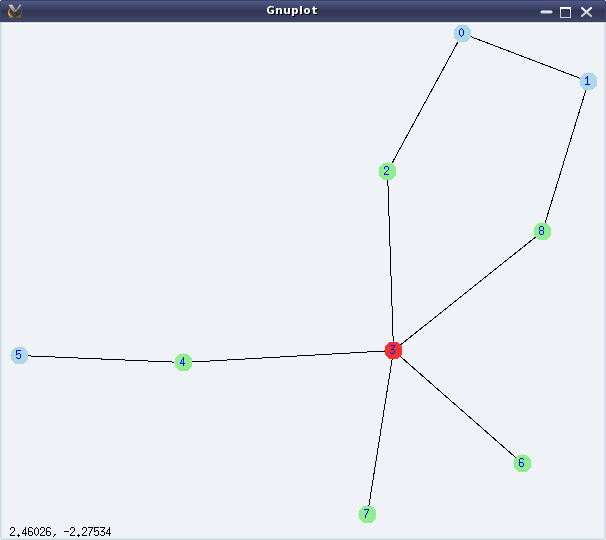
Figure 29: Graph connectivities

Figure 29: Graph connectivities

Vertex 3 is the only centre of the graph and 0, 1, 5 are the peripheral vertices of the graph.

Graph colouring

Graph colouring has been a fascinating topic in graph theory, since its inception. It is all about colouring the vertices or edges of a graph in such a way that no adjacent elements (vertex or edge) have the same colour.

Smallest number of colours needed to colour the vertices of a graph, such that no two adjacent vertices have the same colour, is called the chromatic number of the graph. chromatic_number(<g>) computes the same. vertex_coloring(<g>) returns a list representing the colouring of the vertices of <g>, along with the chromatic number.

Smallest number of colours needed to colour the edges of a graph, such that no two adjacent edges have the same colour, is called the chromatic index of the graph. chromatic_index(<g>) computes the same. edge_coloring(<g>) returns a list representing the colouring of the edges of <g>, along with the chromatic index.

The following demonstration continues colouring the graph from the above demonstration:

(%i12) chromatic_number(g);
(%o12)                                 3
(%i13) vc: vertex_coloring(g);
(%o13) [3, [[0, 3], [1, 1], [2, 2], [3, 1], [4, 2], [5, 1], [6, 2], [7, 2], [8, 2]]]
(%i14) chromatic_index(g);
(%o14)                                 5
(%i15) ec: edge_coloring(g);
(%o15) [5, [[[0, 1], 1], [[0, 2], 2], [[1, 8], 2], [[3, 8], 5], [[2, 3], 1], 
                           [[3, 4], 2], [[4, 5], 1], [[3, 6], 3], [[3, 7], 4]]]
(%i16) draw_graph(g, vertex_coloring=vc, edge_coloring=ec, vertex_size=5,
        edge_width=3, show_id=true)$
(%i17) quit();

Figure 30 shows the coloured version of the graph, as obtained by %i16.
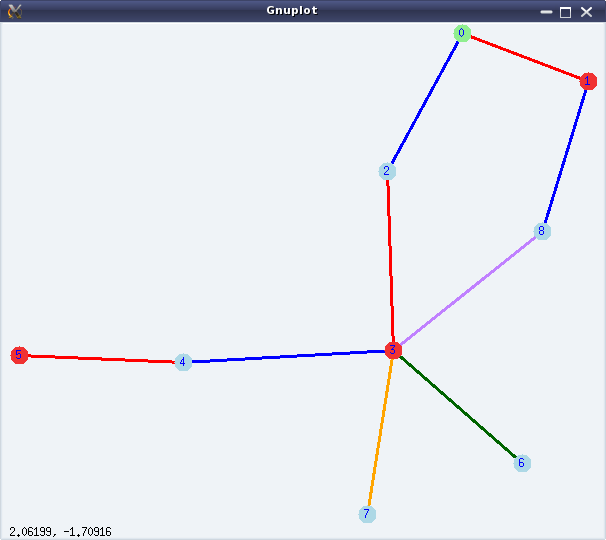
Figure 30: Graph colouring

Figure 30: Graph colouring

Bon voyage

With this article, we have completed a 2 year long mathematical journey through open source, starting from mathematics in Shell, covering Bench Calculator, Octave, and finally concluding with Maxima. I take this opportunity to thank my readers and wish them bon voyage with whatever they have gained through our interactions. However, this is not the end – get set for our next odyssey.
   Send article as PDF   

The Semester Project – Part VI: File System on Block Device

This twenty-third article, which is part of the series on Linux device drivers, enhances the previously written bare bone file system module, to connect with a real hardware partition.

<< Twenty-second Article

Since the last bare bone file system, the first thing which Pugs figured out was how to read from the underlying block device. Following is a typical way of doing it:

struct buffer_head *bh;

bh = sb_bread(sb, block); /* sb is the struct super_block pointer */
// bh->b_data contains the data
// Once done, bh should be released using:
brelse(bh);

To do the above and various other real SFS (Simula File System) operations, Pugs’ felt a need to have his own handle to be a key parameter, which he added as follows (in previous real_sfs_ds.h):

typedef struct sfs_info
{
	struct super_block *vfs_sb; /* Super block structure from VFS for this fs */
	sfs_super_block_t sb; /* Our fs super block */
	byte1_t *used_blocks; /* Used blocks tracker */
} sfs_info_t;

The main idea behind this was to put all required static global variables in a single structure, and point that by the private data pointer of the file system, which is s_fs_info pointer in the struct super_block structure. With that, the key changes in the fill_super_block() (in previous real_sfs_bb.c file) becomes:

  • Allocate the structure for the handle, using kzalloc()
  • Initialize the structure for the handle (through init_browsing())
  • Read the physical super block, verify and translate info from it into the VFS super block (through init_browsing())
  • Point it by s_fs_info (through init_browsing())
  • Update the VFS super block, accordingly

Accordingly, the error handling code would need to do the shut_browsing(info) and kfree(info). And, that would additionally also need to go along with the function corresponding to the kill_sb function pointer, defined in the previous real_sfs_bb.c by kill_block_super, called during umount.

Here’s the various code pieces:

#include <linux/slab.h> /* For kzalloc, ... */
...
static int sfs_fill_super(struct super_block *sb, void *data, int silent)
{
	sfs_info_t *info;

	if (!(info = (sfs_info_t *)(kzalloc(sizeof(sfs_info_t), GFP_KERNEL))))
		return -ENOMEM;
	info->vfs_sb = sb;
	if (init_browsing(info) < 0)
	{
		kfree(info);
		return -EIO;
	}
	/* Updating the VFS super_block */
	sb->s_magic = info->sb.type;
	sb->s_blocksize = info->sb.block_size;
	sb->s_blocksize_bits = get_bit_pos(info->sb.block_size);

	...
}

static void sfs_kill_sb(struct super_block *sb)
{
	sfs_info_t *info = (sfs_info_t *)(sb->s_fs_info);

	kill_block_super(sb);
	if (info)
	{
		shut_browsing(info);
		kfree(info);
	}
}

kzalloc() in contrast to kmalloc(), also zeroes out the allocated location. get_bit_pos() is a simple Pugs’ way to compute logarithm base 2, as follows:

static int get_bit_pos(unsigned int val)
{
	int i;

	for (i = 0; val; i++)
	{
		val >>= 1;
	}
	return (i - 1);
}

And init_browsing(), shut_browsing() are basically the transformations of the earlier user-space functions of browse_real_sfs.c into kernel-space code real_sfs_ops.c, prototyped in real_sfs_ops.h. This basically involves the following transformations:

  • int sfs_handle” into “sfs_info_t *info
  • lseek() & read() into the read from the block device using sb_bread()
  • calloc() into vmalloc() & then appropriate initialization by zeros.
  • free() into vfree()

Here’s the transformed init_browsing() and shut_browsing() in real_sfs_ops.c:

#include <linux/fs.h> /* For struct super_block */
#include <linux/errno.h> /* For error codes */
#include <linux/vmalloc.h> /* For vmalloc, ... */

#include "real_sfs_ds.h"
#include "real_sfs_ops.h"

int init_browsing(sfs_info_t *info)
{
	byte1_t *used_blocks;
	int i, j;
	sfs_file_entry_t fe;
	int retval;

	if ((retval = read_sb_from_real_sfs(info, &info->sb)) < 0)
	{
		return retval;
	}
	if (info->sb.type != SIMULA_FS_TYPE)
	{
		printk(KERN_ERR "Invalid SFS detected. Giving up.\n");
		return -EINVAL;
	}

	/* Mark used blocks */
	used_blocks = (byte1_t *)(vmalloc(info->sb.partition_size));
	if (!used_blocks)
	{
		return -ENOMEM;
	}
	for (i = 0; i < info->sb.data_block_start; i++)
	{
		used_blocks[i] = 1;
	}
	for (; i < info->sb.partition_size; i++)
	{
		used_blocks[i] = 0;
	}

	for (i = 0; i < info->sb.entry_count; i++)
	{
		if ((retval = read_from_real_sfs(info,
					info->sb.entry_table_block_start,
					i * sizeof(sfs_file_entry_t),
					&fe, sizeof(sfs_file_entry_t))) < 0)
		{
			vfree(used_blocks);
			return retval;
		}
		if (!fe.name[0]) continue;
		for (j = 0; j < SIMULA_FS_DATA_BLOCK_CNT; j++)
		{
			if (fe.blocks[j] == 0) break;
			used_blocks[fe.blocks[j]] = 1;
		}
	}

	info->used_blocks = used_blocks;
	info->vfs_sb->s_fs_info = info;
	return 0;
}
void shut_browsing(sfs_info_t *info)
{
	if (info->used_blocks)
		vfree(info->used_blocks);
}

Similarly, all other functions in browse_real_sfs.c would also have to be transformed, one by one. Also, note the read from the underlying block device is being captured by the two functions, namely read_sb_from_real_sfs() and read_from_real_sfs(), which are coded as follows:

#include <linux/buffer_head.h> /* struct buffer_head, sb_bread, ... */
#include <linux/string.h> /* For memcpy */

#include "real_sfs_ds.h"

static int read_sb_from_real_sfs(sfs_info_t *info, sfs_super_block_t *sb)
{
	struct buffer_head *bh;

	if (!(bh = sb_bread(info->vfs_sb, 0 /* Super block is the 0th block */)))
	{
		return -EIO;
	}
	memcpy(sb, bh->b_data, SIMULA_FS_BLOCK_SIZE);
	brelse(bh);
	return 0;
}
static int read_from_real_sfs(sfs_info_t *info, byte4_t block,
				byte4_t offset, void *buf, byte4_t len)
{
	byte4_t block_size = info->sb.block_size;
	byte4_t bd_block_size = info->vfs_sb->s_bdev->bd_block_size;
	byte4_t abs;
	struct buffer_head *bh;

	/*
	 * Translating the real SFS block numbering to underlying block device
	 * block numbering, for sb_bread()
	 */
	abs = block * block_size + offset;
	block = abs / bd_block_size;
	offset = abs % bd_block_size;
	if (offset + len > bd_block_size) // Should never happen
	{
		return -EINVAL;
	}
	if (!(bh = sb_bread(info->vfs_sb, block)))
	{
		return -EIO;
	}
	memcpy(buf, bh->b_data + offset, len);
	brelse(bh);
	return 0;
}

All the above code pieces put in together as the real_sfs_minimal.c (based on the file real_sfs_bb.c created earlier), real_sfs_ops.c, real_sfs_ds.h (based on the same file created earlier), real_sfs_ops.h, and a supporting Makefile, along with the previously created format_real_sfs.c application are available from rsfs_on_block_device_code.tbz2.

Real SFS on block device

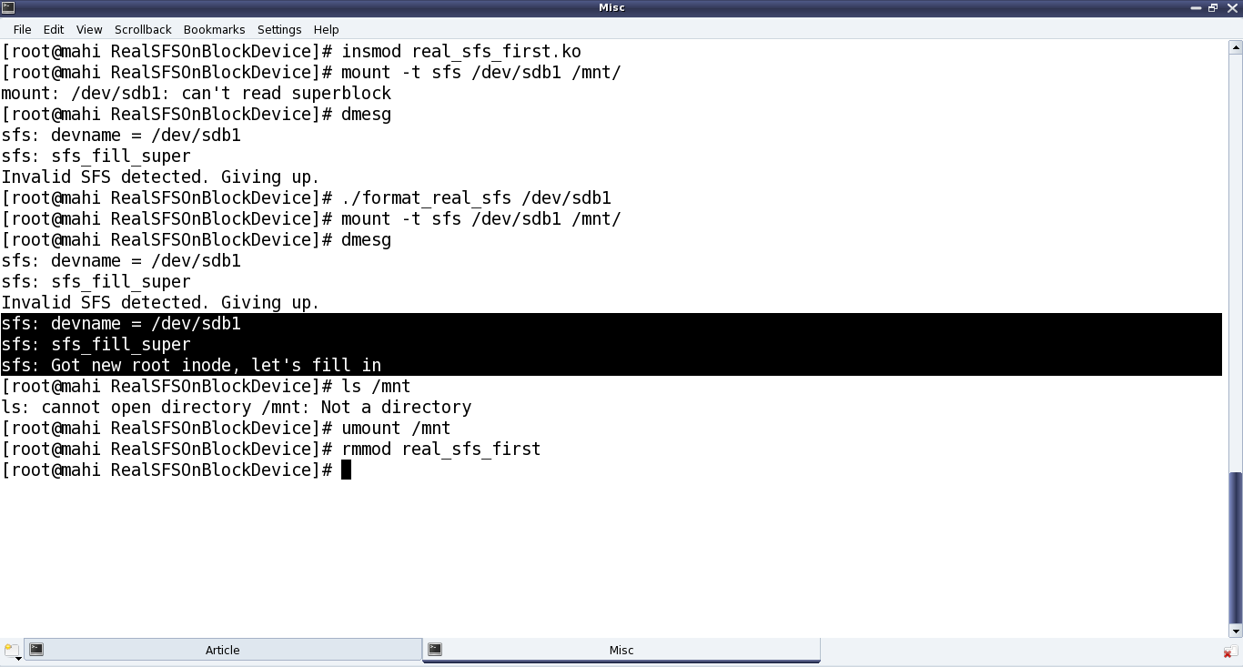
Once compiled using make, getting the real_sfs_first.ko driver, Pugs didn’t expect it to be way different from the previous real_sfs_bb.ko driver, but at least now it should be reading and verifying the underlying partition. And for that he first tried mounting the usual partition of a pen drive to get an “Invalid SFS detected” message in dmesg output; and then after formatting it. Note the same error of “Not a directory”, etc as in previous article, still existing – as anyways it is still very similar to the previous bare bone driver – the core functionalities yet to be implemented – just that it is now on a real block device partition. Figure 39 shows the exact commands for all these steps.

Figure 39: Connecting the SFS module with the pen drive partition

Figure 39: Connecting the SFS module with the pen drive partition

Note: “./format_real_sfs” and “mount” commands may take lot of time (may be in minutes), depending on the partition size. So, preferably use a partition, say less than 1MB.

With this important step of getting the file system module interacting with the underlying block device, the last step for Pugs would be to do the other transformations from browse_real_sfs.c and accordingly use them in the SFS module.

Twenty-fourth Article >>

   Send article as PDF