This 23rd article in the series of “Do It Yourself: Electronics”, generates a desired width pulse using IC 555.
After the square wave experiments, Pugs got more interested in understanding all the working modes of 555. His further studies revealed to him that 555 has basically three modes of operation:
- Astable – Both high & low outputs are unstable and keeps on oscillating to the other, i.e. high to low and low to high. So, also called oscillator. Examples include all the square wave generation, experimented till now, in the previous articles.
- Monostable – Exactly one (mono) of the outputs either high or low is a stable state. However, on an external trigger, it temporarily goes to the other unstable state, stays there for a predefined time and comes back to the stable state, on its own. This is what Pugs is planning to explore further by using a switch for the trigger. The pulse width of the unstable state is decided by the resistor and capacitor in the circuit. As it generates single (mono) pulse on trigger, it is also called monoshot configuration.
- Bistable – Both high & low outputs are stable, meaning the circuit remains in the state it is in, unless triggered externally to go otherwise. A typical usage of this could be a NOT gate kind of level inversion. Pugs plans to explore this in his next experimentation.
Now interestingly, the mono stability could be either in the low output or the high output. Correspondingly, the pulse would be high or low, and the trigger accordingly would be low or high. And for each of these the circuits are slightly different, especially from the perspective as to where the trigger is applied. Recall that voltage below 1/3 of Vcc on trigger pin 2 triggers output Vo pin 3 to high and voltage above 2/3 of Vcc on threshold pin 6 brings back output Vo pin 3 to low.
Below are the corresponding schematics, and the breadboard connections made by Pugs:
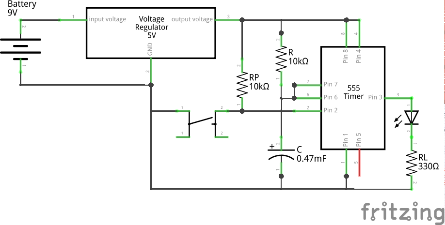
Monostable Low (High Pulse) using 555 (Schematic)
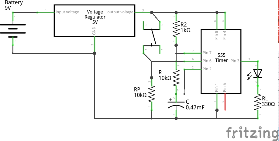
Monostable High (Low Pulse) using 555 (Schematic)
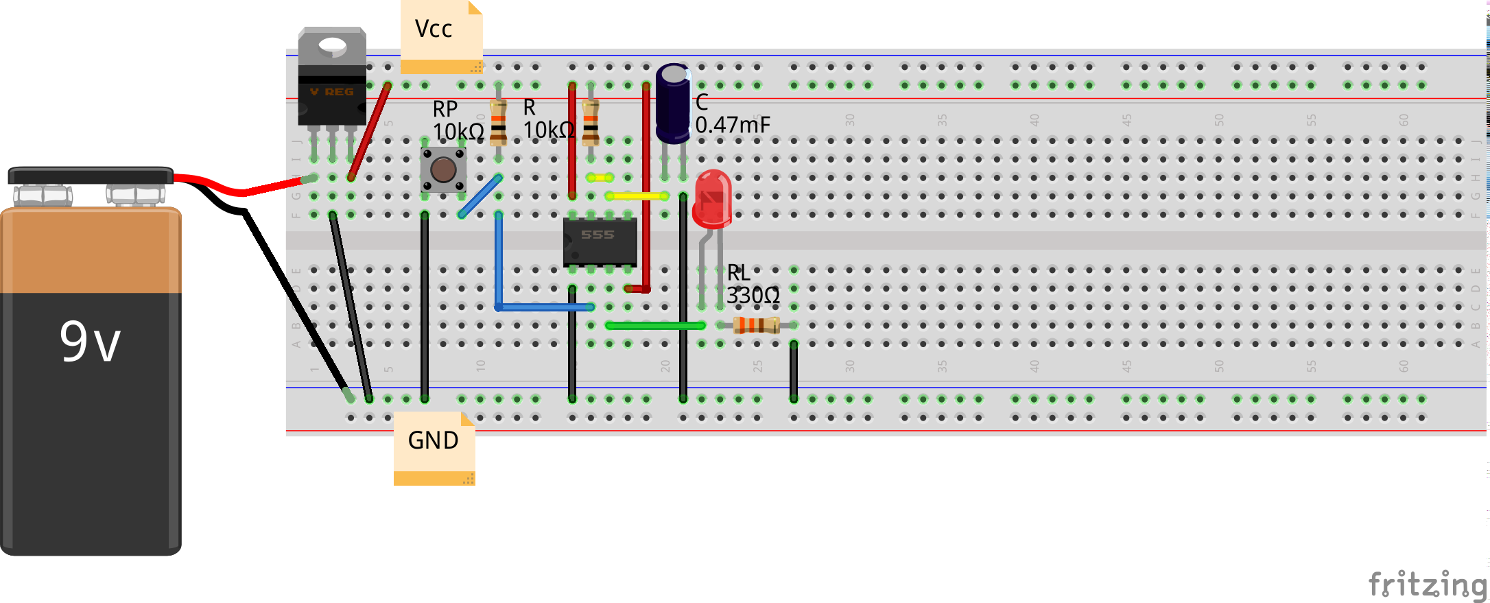
Monostable Low (High Pulse) using 555 (Breadboard)
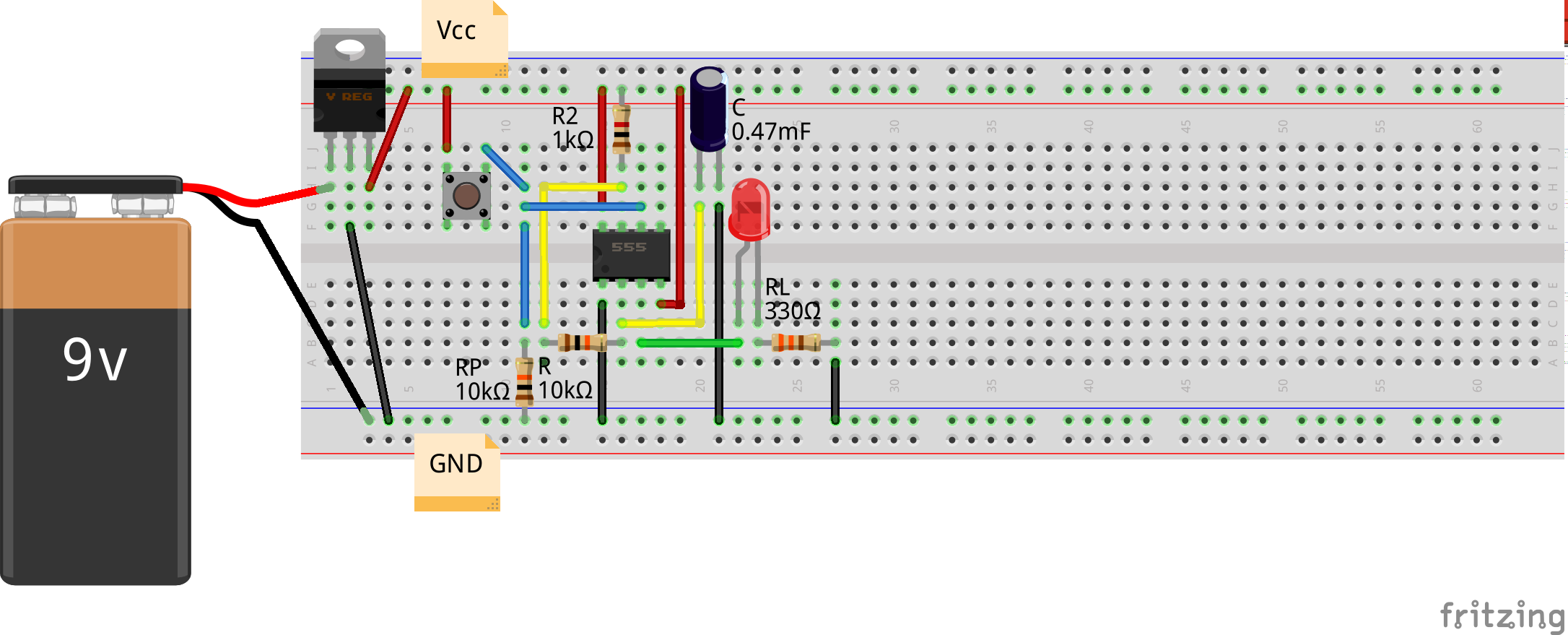
Monostable High (Low Pulse) using 555 (Breadboard)
Observe that in either case, the trigger is being achieved on press of the switch. However, for triggering the high pulse (on Vo), Pugs needs to connect the pulled up switch output to trigger pin 2. And, for triggering the low pulse (on Vo), Pugs needs to connect the pulled down switch output to threshold pin 6. Also, note that in the first case, the final output Vo is brought back low by charging the capacitor connected to the threshold pin 6, to 2/3 of Vcc through R. And in the second case, the final output Vo is brought back high by discharging the capacitor connected to the trigger pin 2, to 1/3 of Vcc through R. And hence, in either case, the pulse width (time from trigger to restoration of stable state) would be decided by the following equation:
")
One may derive this, using the methodology similar to the one used in this previous article. So, it is left to the reader to derive the same.
Pugs tried the first (monostable at low output) experiment using two set of values: (1) R = 10KΩ, C = 100μF, (2) R = 10KΩ, C = 470μF. Using (6), the corresponding pulse widths are expected to be approximately 1 and 5 seconds.
And then he tried the second (monostable at high output) experiment using R = 10KΩ, C = 470μF. Using (6), the expected pulse width is approximately 5 seconds.
As in previous articles, Pugs tried observing the Vo output waveforms on the home-made PC oscilloscope, as created in his previous PC Oscilloscope article. But he observed nothing other than noise, except some change when he presses the switch. This reminded him that the home-made PC oscilloscope filters out low frequency (DC) voltages, and with such low frequency Vo, there would be nothing left to observe after filtering, except when there is some change on switch press. So, Pugs decided to rather use a multimeter. But, then got the idea of putting an LED instead, which is what is visible in the above circuitries.
And here are the three video clips of the LED blinkings observed in the three cases:
(1) 1 second high pulse (monostable low)
(2) 5 second high pulse (monostable low)
(3) 5 second low pulse (monostable high)
Observe the closeness of the pulse width timing (with a watch) from the above videos compared with the expected values.
Also note that during the low pulse (monostable high) experiment, Pugs is waiting for another 5+ seconds after the output Vo is high, before pressing the switch again. In fact, when he tried doing it without waiting, this is what he observed:
That’s weird – the pulse width also has reduced. But why is that? Possibly, because the capacitor is not charged back to the full, before the switch press and so it got discharged faster. That brings to the point, that derivation of equation 6 assumes that the capacitor is completely discharged in the first case (monostable low) and completely charged in the second case (monostable high), before the trigger. If not, the calculations would vary. Now, in the first case the capacitor gets immediately discharged as it is directly grounded through discharge pin 7. So, such scenario wouldn’t happen with that. However, in second case the charging is through resistors R & R1, so that would take its own time based on the RC value, which in the above case is 5+ seconds ((10 + 1)K * 470u). To avoid this, Pugs possibly would have to by-pass the big R in the charging cycle by putting a diode in parallel with R. If you believe it, go ahead and try it out.
Note: R1 has been taken small compared to R, exactly for reducing the RC effect. However, it cannot be made zero, as that would short the Vcc & GND (from discharge pin 7) when the low pulse is getting output on Vo.