Category Archives: Electronics

Electronics from Scratch w/ Friends

Programming the I2C protocol

This 14th article in the series of “Do It Yourself: Electronics”, demonstrates programming the I2C protocol for the AVR micro-controller ATmega16.

<< Previous Article

Equipped with debugging power, Pugs dwelled further into stuff of more involved programming – the protocols – specifically the I2C protocol.

What is I2C protocol?

It is a 2-wire protocol to communicate between a master controller with its slave devices, which understand the same protocol. Physically, it consists of communication over two wires or lines, namely SDA and SCL – the data & clock lines. The data could be clocked either at 100kbps (standard mode) or 400kbps (fast mode). Many slaves can be connected on the same I2C bus. Hence, each slave is identified by a unique 7-bit address. Overall the communication can be summarized as follows:

For Master Transmission to Slave, a single transaction typically goes like this:

  • Indicate START of communication
  • Send out the slave address of the device to transmit to
  • Send out the data
  • Indicate STOP of communication

There may be confirmation handshakings using acknowledgments at various stages of the transaction.

For Master Reception from Slave, a single transaction typically goes like this:

  • Indicate START of communication
  • Send out the slave address of the device to receive from
  • Receive the data
  • Indicate STOP of communication

Here also, there may be confirmation handshakings using acknowledgments at various stages of the transaction, except typically the last one.

Many a times a transaction consisting of both transmission & reception is needed. That would go as follows:

  • Indicate START of communication
  • Send out the slave address of the device to transmit to
  • Send out the data
  • Indicate (re)START of communication
  • Send out the slave address of the device to receive from
  • Receive the data
  • Indicate STOP of communication

Notice that there is no stop indication between the transmit and receive, and the second start is very often termed as restart.
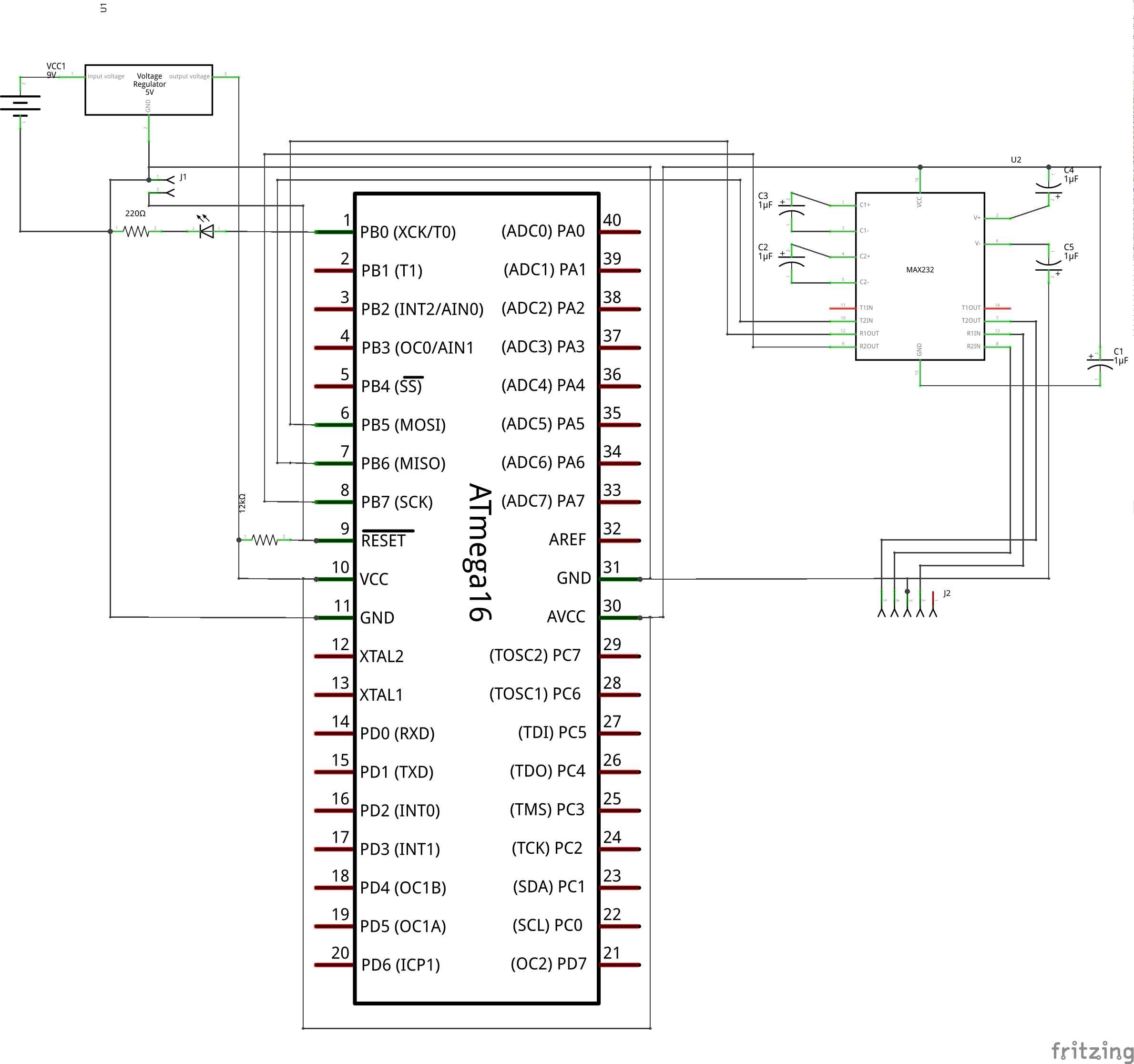
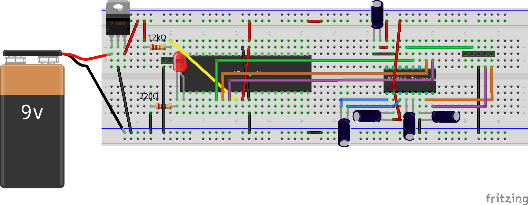
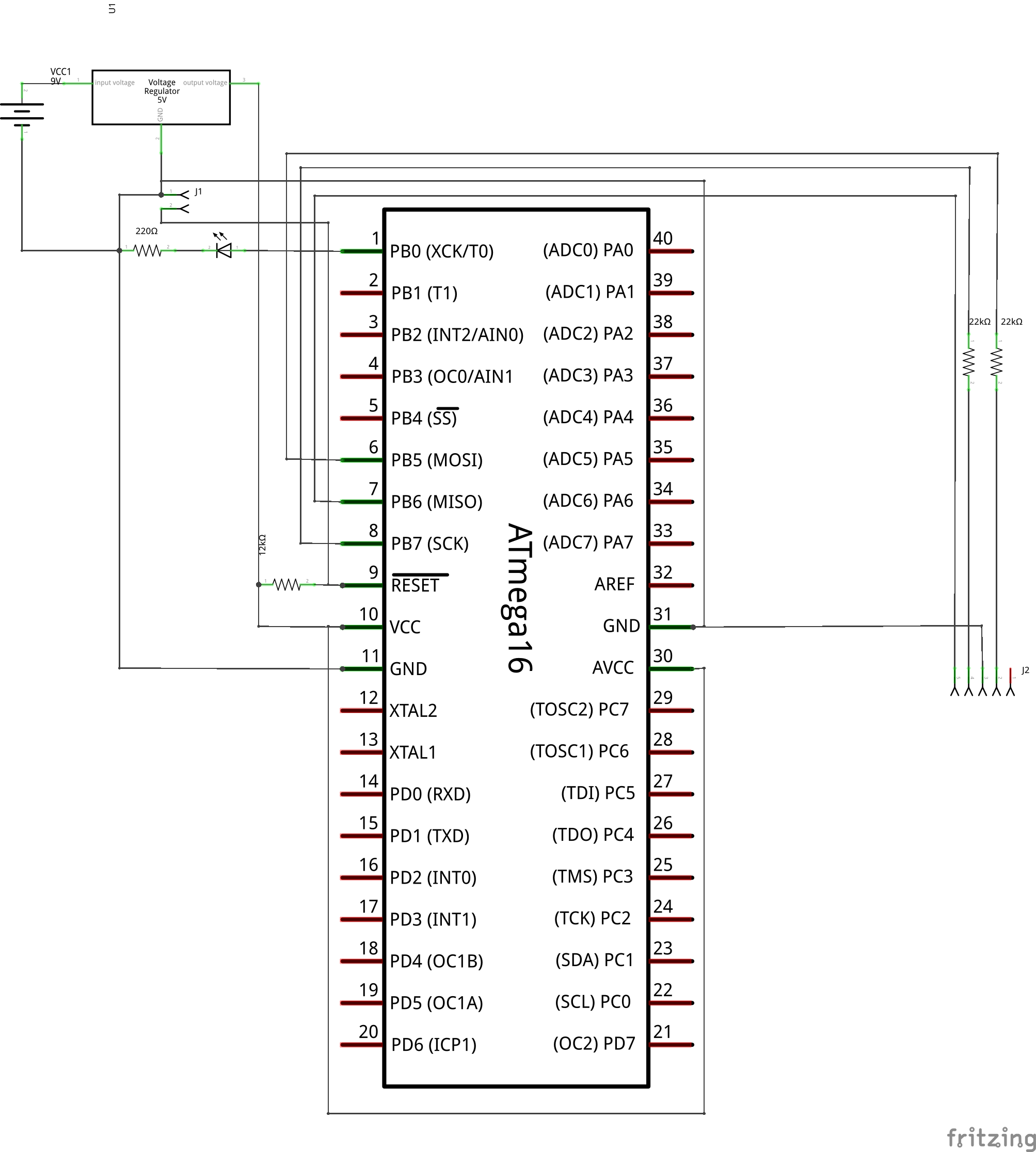
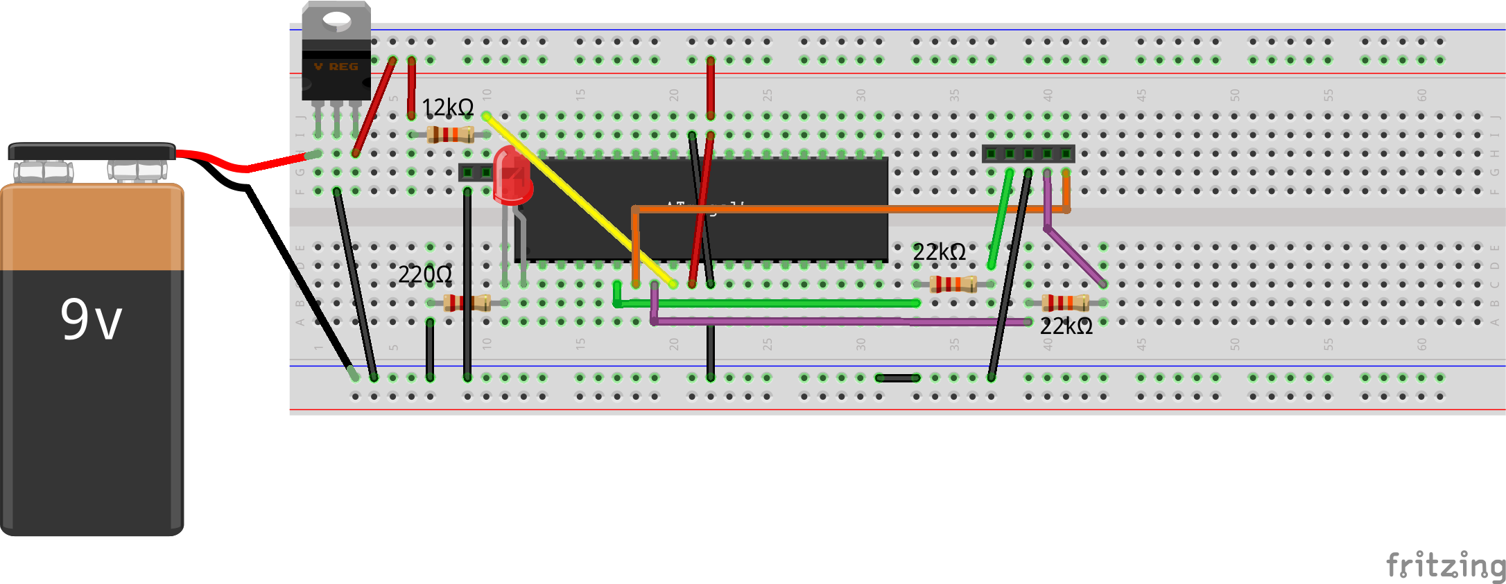
I2C on ATmega16

Based on the above principle, the 2-wire interface (TWI) for ATmega16 to behave as a master is implemented using just 4 registers:

  • Bit rate register TWBR to set up the data transfer rate along with TWPS bits in TWSR register
  • Control register TWCR for all controls including start (TWSTA), stop (TWSTO), ack (TWEN), enable (TWEN), interrupt (TWINT) using corresponding bits mentioned in the ()
  • Status register TWSR for the transaction status
  • Data register TWDR for transmitting and receiving data

Now, formula for the bit rate is given by:
f_{SCL} = \frac{f_{cpu}}{16 + 2 . {TWBR} . 4^{TWPS}}
where TWBR & TWPS are to be set in the ATmega16 registers.

On analyzing the formula, one would figure out that, we may not be able to use TWI at either 100kbps or 400kbps with the 1 MHz (f_{cpu}) default clock of the ATmega16, as there exists no values for TWBR & TWPS to achieve the same. So, we would need to change the fuse settings of ATmega16, to get a different clock. We would do that when downloading our code, say to 8MHz, the maximum possible without an external crystal. Assuming that, the values for TWBR and TWPS for the standard and fast bit rates would come out as follows:

  • Standard: 32 & 0
  • Fast: 2 & 0

Using all these information as per the ATmega16 datasheet pg 177-200, the TWI can be prototyped & programmed as follows in twi.h & twi.c, respectively. The header twi.h would be:

#ifndef TWI_H
#define TWI_H

typedef enum
{
	standard,
	fast
} TwiMode;

void twi_init(TwiMode mode);
void twi_shut(void);
int twi_master_tx(uint8_t addr, uint8_t *data, int len);
int twi_master_rx(uint8_t addr, uint8_t *data, int len);
int twi_master_tx_rx(uint8_t addr, uint8_t *tx_data, int tx_len, uint8_t *rx_data,
			int rx_len);
#endif

And the complete implementation of twi.c goes here:

#include <avr/io.h>

#include "twi.h"

#define QUIT_TWI_OP { send_stop(); return -1; }

typedef enum
{
	/* TWI Master Status Codes */
	st_start = 0x08,
	st_restart = 0x10,
	st_sla_w_ack = 0x18,
	st_sla_w_noack = 0x20,
	st_data_w_ack = 0x28,
	st_data_w_noack = 0x30,
	st_arb_lost = 0x38,
	st_sla_r_ack = 0x40,
	st_sla_r_noack = 0x48,
	st_data_r_ack = 0x50,
	st_data_r_noack = 0x58,
} TwiStatus;
typedef enum
{
	dir_write,
	dir_read
} TwiOperation;

void twi_init(TwiMode mode)
{
	// 1 = output, 0 = input
	DDRC &= ~0b00000011; // PC0 = SCL; PC1 = SDA
	PORTC |= 0b00000011; // Internal pull-up on both lines

	TWBR = (mode == standard) ? 32 : 2;
	TWSR &= ~(0b11 << TWPS0); // Clearing TWSP to 0

	TWCR |= (1 << TWEN); // Enable TWI, generating the SCLK
}
void twi_shut(void)
{
	TWCR &= ~(1 << TWEN); // Disable TWI

	TWBR = 0;
	TWSR &= ~(0b11 << TWPS0);

	// 1 = output, 0 = input
	DDRC &= ~0b00000011; // PC0 = SCL; PC1 = SDA
	PORTC &= ~0b00000011; // Clear pull-up on both lines
}

static uint8_t get_status(uint8_t status)
{
	uint8_t st;

	while (!(TWCR & (1 << TWINT)))
		;
	if ((st = (TWSR & 0xF8)) == status)
		return 0;
	else
		return st;
}
static int send_start(uint8_t status)
{
	TWCR = (1 << TWINT) | (1 << TWSTA) | (1 << TWEN);
	return get_status(status);
}
static void send_stop(void)
{
	TWCR = (1 << TWINT) | (1 << TWSTO) | (1 << TWEN);
}
static int send_data(uint8_t data, uint8_t status)
{
	TWDR = data;
	TWCR = (1 << TWINT) | (1 << TWEN);
	return get_status(status);
}
static int recv_data(uint8_t *data, uint8_t status, uint8_t ack)
{
	TWCR = (1 << TWINT) | (ack << TWEA) | (1 << TWEN);
	if (get_status(status) == 0)
	{
		*data = TWDR;
		return 0;
	}
	else
	{
		return -1;
	}
}

int twi_master_tx(uint8_t addr, uint8_t *data, int len)
{
	int i;

	if (send_start(st_start)) QUIT_TWI_OP;
	if (send_data((addr << 1) | dir_write, st_sla_w_ack)) QUIT_TWI_OP;
	for (i = 0; i < len; i++)
	{
		if (send_data(data[i], st_data_w_ack)) QUIT_TWI_OP;
	}
	send_stop();
	return 0;
}
int twi_master_rx(uint8_t addr, uint8_t *data, int len)
{
	int i;

	if (send_start(st_start)) QUIT_TWI_OP;
	if (send_data((addr << 1) | dir_read, st_sla_r_ack)) QUIT_TWI_OP;
	for (i = 0; i < len - 1; i++)
	{
		if (recv_data(&data[i], st_data_r_ack, 1)) QUIT_TWI_OP;
	}
	if (recv_data(&data[i], st_data_r_noack, 0)) QUIT_TWI_OP;
	send_stop();
	return 0;
}
int twi_master_tx_rx(uint8_t addr, uint8_t *tx_data, int tx_len, uint8_t *rx_data,
			int rx_len)
{
	int i;

	if (send_start(st_start)) QUIT_TWI_OP;
	if (send_data((addr << 1) | dir_write, st_sla_w_ack)) QUIT_TWI_OP;
	for (i = 0; i < tx_len; i++)
	{
		if (send_data(tx_data[i], st_data_w_ack)) QUIT_TWI_OP;
	}
	if (send_start(st_restart)) QUIT_TWI_OP;
	if (send_data((addr << 1) | dir_read, st_sla_r_ack)) QUIT_TWI_OP;
	for (i = 0; i < rx_len - 1; i++)
	{
		if (recv_data(&rx_data[i], st_data_r_ack, 1)) QUIT_TWI_OP;
	}
	if (recv_data(&rx_data[i], st_data_r_noack, 0)) QUIT_TWI_OP;
	send_stop();
	return 0;
}

All coded for the AVR master, but how to test without a slave. Exactly for that, we need a I2C device, say a real time clock (RTC). We would connect one, say the chip DS1307, and try it out in our next article. Till then, thrash out your understanding on the above I2C implementation and get the DS1307 chip and 32768Hz (clock) crystal ready.

Next Article >>

   Send article as PDF   

Debugging Micro-controller Programs over USART

This 13th article in the series of “Do It Yourself: Electronics”, demonstrates debugging of micro-controller programs over the USART.

<< Previous Article

With the working of the basic serial functionality, one can directly use that for debugging by logging on serial console. However, Pugs wanted to make it more sophisticated. So, he turned the earlier serial.c into a library file by including serial.h in it, and removing main() from it, with the corresponding function prototypes added into the new file serial.h. With that the serial.h looks as follows:

#ifndef SERIAL_H

#define SERIAL_H

#include <avr/io.h>

void usart_init(unsigned long baud);
void usart_shut(void);
void usart_byte_tx(uint8_t data);
int usart_byte_available(void);
uint8_t usart_byte_rx(void);
void usart_tx(char *str);
void usart_rx(char *str, int max_len);

#endif

Then, the debugging wrapper functions were implemented in debug.c with the following prototypes in debug.h:

#ifndef DEBUG_H

#define DEBUG_H

#include <avr/io.h>

void debug_init(void);
void debug_shut(void);
void print_nl(void);
void print_str(char *str);
void print_str_nl(char *str);
void print_num(uint32_t n);
void print_hex(uint32_t n);
char scan_char(void);
void scan_line(char *line, int max_len);

#endif

The complete implementation of debug.c goes here:

#include "serial.h"
#include "debug.h"

void debug_init(void)
{
	usart_init(9600);
}
void debug_shut(void)
{
	usart_shut();
}

void print_nl(void)
{
	usart_tx("\r\n");
}
void print_str(char *str)
{
	usart_tx(str);
}
void print_str_nl(char *str)
{
	usart_tx(str);
	usart_tx("\r\n");
}
void print_num(uint32_t n)
{
	int i;
	char num[11];

	for (i = 9; i >= 0; i--)
	{
		num[i] = '0' + (n % 10);
		n /= 10;
	}
	num[10] = 0;
	usart_tx(num);
}
void print_hex(uint32_t n)
{
	int i;
	char c;

	usart_byte_tx('0');
	usart_byte_tx('x');
	for (i = 7; i >= 0; i--)
	{
		c = ((n >> (i << 2)) & 0xF);
		c += ((c <= 9) ? '0' : (-10 + 'A'));
		usart_byte_tx(c);
	}
}
char scan_char(void)
{
	return usart_byte_rx();
}
void scan_line(char *line, int max_len)
{
	usart_rx(line, max_len);
}

And to test the complete debug library, Pugs wrote the following debug_test.c:

#include <avr/io.h>

#include "debug.h"

int main(void)
{
	char str[32];
	uint32_t value = (1L << 26);

	debug_init();

	scan_char(); // Waiting for a character, typically an 
	print_str_nl("Welcome to SysPlay's serial debugger");
	print_str("(1L << 26) in decimal: ");
	print_num(value);
	print_nl();
	print_str("(1L << 26) in hexadecimal: ");
	print_hex(value);
	print_nl();
	while (1)
	{
		print_str("SysPlay> ");
		scan_line(str, 32);
		print_str("You gave: ");
		print_str(str);
		print_nl();
	}

	debug_shut();

	return 0;
}

Then, Pugs compiled all the programs together as follows:

$ avr-gcc -mmcu=atmega16 -DF_CPU=1000000 -Os debug_test.c serial.c debug.c -o
debug_test.elf
$ avr-objcopy -O ihex debug_test.elf debug_test.hex

And finally, downloaded the debug_test.hex into the ATmega16 with J1 shorted (same as in the previous articles), using the following command:

$ avrdude -c ponyser -P /dev/ttyUSB0 -p m16 -U flash:w:debug_test.hex:i

Pugs then connected the USB to TTL converter to his laptop on the USB side, and the RX, TX, GND pins of the USB to TTL converter to the TXD, RXD, GND pins of the micro-controller. And started the serial application minicom as root on his laptop as follows:

# minicom -D /dev/ttyUSB1 -b 9600 -o

Note that Pugs’ TTL to USB connector shows up as /dev/ttyUSB1 on his laptop. In case, yours is different, use that instead. And then, as soon as Pugs removed the jumper J1, he got the value printed in decimal and then in hexadecimal followed by the “SysPlay> ” prompt for taking string inputs and displaying them back. To see what he was typing, Pugs typed Ctrl-A E on minicom. And, to quit from minicom, Pugs typed Ctrl-A Q.

Next Article >>

   Send article as PDF   

Micro-controller USART Interaction

This 12th article in the series of “Do It Yourself: Electronics”, demonstrates setting up of USART communication with a micro-controller.

<< Previous Article

While trying out the various micro-controller programs, Rohit or for that matter even Pugs had many times faced a dire need for something more than blinking a LED but simple enough to debug their programs – something like printf(). And that brings them to the ubiquitous serial communication over serial port or the USART (Universal Synchronous Asynchronous serial Receiver Transmitter). Though it is vanishing from today’s PCs & laptops, almost every embedded device has it. And so is it with the ATmega16/32 – it has the pins 14 (PD0 / RXD) and 15 (PD1 / TXD) respectively for receiving and transmitting data serially. However, these pins operate at TTL voltage levels or so as to say at 0V & 5V in our case. So, if we want to communicate it with our PC, say over USB, we would need a TTL to USB converter. Figure below shows one such hardware readily available in the market.

TTL to USB Converter

TTL to USB Converter

Equipped with the information above, and a walk through the USART section of ATmega16 datasheet pg 144-171, lead to the following programming conclusions:

  • USART needs to be configured for baud rate aka data bit rate, data bit length, stop bit count, parity type
  • These configurations are achieved by programming the following registers: UBRRH, UBRRL for baud rate; UCSRB, UCSRC for others
  • Data transmission and reception are achieved for every data byte wrote in /read from the USART I/O Data (UDR) register
  • Before transmission and reception, the corresponding TXEN and RXEN bit need to be set in UCSRB register
  • On completion of transmission and reception, the corresponding TXC and RXC bits in UCSRA register are set
  • UDRE bit in UCSRA indicates state of the data register, ‘1’ meaning empty and ready to be written

Having obtained the above information, along with the following baud rate formula (from the ATmega16 datasheet pg 147):

baud = \frac{f_{cpu}}{16 . (UBRR + 1)}

Pugs coded the following serial.c:

#include <avr/io.h>

typedef enum
{
	p_none,
	p_even,
	p_odd
} Parity;

static void set_baud(unsigned long baud)
/*
 * For default of Asynchronous mode and for USART0.
 * For Normal mode: baud = (F_CPU / (16 * (UBRR + 1)))
 */
{
	uint16_t ubrr;

	ubrr = (F_CPU / 16 / baud) - 1;
	UBRRH = (uint8_t)(ubrr >> 8);
	UBRRL = (uint8_t)(ubrr);
}
static void set_format(uint8_t data_bits, Parity parity, uint8_t stop_bits)
{
	uint8_t control = (1 << URSEL);

	switch (data_bits)
	{
		case 5:
			control |= (0b00 << UCSZ0);
			// And, UCSRB &= ~(1 << UCSZ2);
			break;
		case 6:
			control |= (0b01 << UCSZ0);
			// And, UCSRB &= ~(1 << UCSZ2);
			break;
		case 7:
			control |= (0b10 << UCSZ0);
			// And, UCSRB &= ~(1 << UCSZ2);
			break;
		case 8:
		default:
			control |= (0b11 << UCSZ0);
			// And, UCSRB &= ~(1 << UCSZ2);
			break;
		case 9:
			control |= (0b11 << UCSZ0);
			// And, UCSRB |= (1 << UCSZ2);
			break;
	}
	switch (parity)
	{
		case p_none:
		default:
			control |= (0b00 << UPM0);
			break;
		case p_even:
			control |= (0b10 << UPM0);
			break;
		case p_odd:
			control |= (0b11 << UPM0);
			break;
	}
	switch (stop_bits)
	{
		case 1:
		default:
			control |= (0b0 << USBS);
			break;
		case 2:
			control |= (0b1 << USBS);
			break;
	}

	if (data_bits == 9)
		UCSRB |= (1 << UCSZ2);
	else
		UCSRB &= ~(1 << UCSZ2);
	UCSRC = control;
}

static void usart_enable(void)
{
	/* Enable receiver and transmitter */
	UCSRB |= (1 << RXEN) | (1 << TXEN);
}
static void usart_disable(void)
{
	/* Disable receiver and transmitter */
	UCSRB &= ~((1 << RXEN) | (1 << TXEN));
}

void usart_init(unsigned long baud)
{
	set_baud(baud);

	/* Default frame format: 8 data, No Parity, 1 stop bit (8N1) */
	set_format(8, p_none, 1);

	usart_enable();
}
void usart_shut(void)
{
	usart_disable();
}

void usart_byte_tx(uint8_t data)
{
	/* Wait for empty transmit buffer */
	while (!(UCSRA & (1 << UDRE)))
		;
	/* Put data into buffer, sends the data */
	UDR = data;
}
int usart_byte_available(void)
{
	return (UCSRA & (1 << RXC));
}
uint8_t usart_byte_rx(void)
{
	/* Wait for data to be received */
	while (!(UCSRA & (1 << RXC)))
		;
	/* Get and return received data from buffer */
	return UDR;
}
void usart_tx(char *str)
{
	while (*str)
	{
		usart_byte_tx(*str++);
	}
}
void usart_rx(char *str, int max_len)
{
	int i;

	for (i = 0; i < max_len - 1; i++)
	{
		str[i] = usart_byte_rx();
		if (str[i] == '\n')
			break;
	}
	str[i] = 0;
}

int main(void)
{
	char c;

	usart_init(38400);

	usart_byte_rx(); // Waiting for a character, typically an 
	usart_tx("Welcome to SysPlay's character echoer\r\n");

	while (1)
	{
		usart_tx("SysPlay> ");
		c = usart_byte_rx();
		usart_tx("You gave: ");
		usart_byte_tx(c);
		usart_tx("\r\n");
	}

	usart_shut();

	return 0;
}

Then, Pugs compiled the program as follows (as in the previous articles):

$ avr-gcc -mmcu=atmega16 -DF_CPU=1000000 -Os serial.c -o serial.elf
$ avr-objcopy -O ihex serial.elf serial.hex

And finally, downloaded the serial.hex into the ATmega16 with J1 shorted (same as in the previous articles), using the following command:

$ avrdude -c ponyser -P /dev/ttyUSB0 -p m16 -U flash:w:serial.hex:i

Pugs then connected the USB to TTL converter to his laptop on the USB side, and the RX, TX, GND pins of the USB to TTL converter to the corresponding pins of the micro-controller. And started the serial application minicom as root on his laptop as follows:

# minicom -D /dev/ttyUSB1 -b 38400 -o

Note that Pugs’ TTL to USB connector shows up as /dev/ttyUSB1 on his laptop. In case, yours is different, use that instead. And as usual, it didn’t work in the first shot, even though he removed the jumper J1. After some googling, Pugs realized that it should have been a common sense to connect the RXD of the micro-controller to the TX of the TTL to USB converter and TXD of the micro-controller to the RX of the TTL to USB converter, rather than TXD to TX and RXD to RX, because data transmitted from micro-controller would be received by the USB and vice versa. So, correcting the connections, Pugs got the input character echoing back on the serial console. To see what he was typing, Pugs typed Ctrl-A E on minicom. And, to quit from minicom, Pugs typed Ctrl-A Q.

Given the basic setup and operation of USART achieved, watch out for how Pugs designs a library to do some fancy debugging.

Next Article >>

   Send article as PDF   

Playing Music using a Micro-controller

This 11th article in the series of “Do It Yourself: Electronics”, demonstrates playing various audio frequncies using timer module of a micro-controller.

<< Previous Article

After seeing the dimming power of the timer module of a micro-controller, Rohit was excited enough to experiment with the various other modes of the timer module. The idea of generating waveforms of various frequencies was generating all kind of random thoughts in his head. “Sound is also waves with some frequency – so can I generate sound using the timer?”, was one of the thoughts getting stronger and stronger. He finally decided to try it out.

As he has already tried with the Timer0, this time he thought of giving a try to another similar timer.

“Hey Pugs! Timer2 seems to be similar to Timer0. Can I try similar experiments with that as well?”, quizzed Rohit.

“Yes. Why not? Timer2 is also 8-bit with similar registers and modes”, replied Pugs.

“Also, the ATmega16 datasheet pg 122 mentions that the clear timer on compare match aka CTC mode gives more control to (compare match) output frequency.”

“Yes, it does. So, what are you trying?”

“Just thought of creating some sound.”

“Hmmm! That would be cool. Let’s give it a try.”

Unlike the earlier tried fast PWM mode, the timer counter clears to zero on match with value of OCR2 in CTC mode (WGM2[1:0] = 2), instead of hitting the maximum value. Also, by setting the COM2[1:0] to 1 the output on OC2/PD7 would keep on toggling on every match, thus generating a 50% duty cycle square wave. As per the ATmega16 datasheet pg 123, the waveform frequency would be given by

f = \frac{f_{cpu}}{2 . N . (1 + OCR2)}

where N represents the prescaler, to be set in the same register TCCR2, as the above settings.

“Based on the frequency formula, seems like so many ways to get the same frequency using the various prescaler values. How do we choose the prescaler?”, asked Rohit puzzled with the possibilities.

“Don’t get swayed by that. Note that both OCR2 and prescaler are integral and hence can’t generate all frequencies”, replied Pugs after a keen observation on the formula. “Also, the various N values would give the varying frequency resolutions. Hence, depending on our required resolution and may be range, we’d have to carefully choose the prescaler”, completed Pugs.

“That looks complicated and also interesting. Let me try a few combinations to get a feel of it.”

“Just keep in mind that for your sound generation to be audible, you’d need frequencies only between 20Hz to 20KHz.”

“Yes. Yes. I know that”, quipped Rohit.

Meanwhile, Pugs gave a shot to his shell scripting prowess, and ran the following shell command:

$ for ps in 1 8 32 64 128 256 1024
>do
>	echo -e "\nprescaler = $ps"
>	for ocr2 in `seq 0 255`
>	do
>		echo -n $((500000 / $ps / (1 + $ocr2)))
>		echo -n " "
>	done
>done

And from its output, he got well-interspersed frequencies in the audio frequency range for a prescaler of 8, as follows:

...
prescaler = 8
62500 31250 20833 15625 12500 10416 8928 7812 6944 6250 5681 5208 4807 4464 4166 3906
3676 3472 3289 3125 2976 2840 2717 2604 2500 2403 2314 2232 2155 2083 2016 1953 1893
1838 1785 1736 1689 1644 1602 1562 1524 1488 1453 1420 1388 1358 1329 1302 1275 1250
1225 1201 1179 1157 1136 1116 1096 1077 1059 1041 1024 1008 992 976 961 946 932 919
905 892 880 868 856 844 833 822 811 801 791 781 771 762 753 744 735 726 718 710 702
694 686 679 672 664 657 651 644 637 631 625 618 612 606 600 595 589 584 578 573 568
563 558 553 548 543 538 534 529 525 520 516 512 508 504 500 496 492 488 484 480 477
473 469 466 462 459 456 452 449 446 443 440 437 434 431 428 425 422 419 416 413 411
408 405 403 400 398 395 393 390 388 385 383 381 378 376 374 372 369 367 365 363 361
359 357 355 353 351 349 347 345 343 341 339 337 336 334 332 330 328 327 325 323 322
320 318 317 315 314 312 310 309 307 306 304 303 301 300 299 297 296 294 293 292 290
289 288 286 285 284 282 281 280 279 277 276 275 274 272 271 270 269 268 267 265 264
263 262 261 260 259 258 257 256 255 254 253 252 251 250 249 248 247 246 245 244
...

So, they decided to go ahead with the prescaler of 8, which translates to CS2[2:0] = 2, and this is what buzzer.c Rohit coded:

/*
 * This example uses CTC mode of 8-bit Timer/Counter2 for generating various
 * audio frequencies on OC2/PD7 (Pin 21).
 * Hence, Buzzer/Speaker is to be connected between OC2/PD7 (Pin 21) & GND.
 */

#include <avr/io.h>
#include <util/delay.h>

#define HUMAN_AUDIBLE_MAX_FREQ 20000

#define PRESCALER (2 << CS20) /* Prescaler N = 8 */
#define N 8
#define MAX_FREQ (F_CPU / (2 * N)) /* F_CPU / (2 * N * (1 + (OCR2 = 0))) */
#define MIN_FREQ (F_CPU / (2 * N * 256)) /* F_CPU / (2 * N * (1 + (OCR2 = 255))) */

void set_frequency(unsigned long freq)
{
	if (freq < MIN_FREQ)
	{
		freq = MIN_FREQ;
	} else if (freq > MAX_FREQ)
	{
		freq = MAX_FREQ;
	}
	/* f = MAX_FREQ / (1 + OCR2), i.e. OCR2 = MAX_FREQ / f - 1; */
	OCR2 = MAX_FREQ / freq - 1;
}
void init_timer(unsigned long freq)
{
	DDRD |= (1 << PD7); // OC2 is PD7 - setting it as output

	set_frequency(freq);

	/*
	 * Setting the Timer/Counter2 in CTC (Clear Timer on Compare) (non-PWM) mode.
	 * Toggling on Match to generate square wave for a particular frequency,
	 * as per the prescaler and OCR2 setting.
	 * Output would come on OC2/PD7 (Pin 21).
	 */
	TCCR2 = (1 << WGM21) | (0 << WGM20) | (1 << COM20) | PRESCALER;
}
void stop_timer(void)
{
	TCCR2 = 0;
}

int main(void)
{
	unsigned long freq = MIN_FREQ;

	init_timer(freq);

	while (1)
	{
		_delay_ms(100);
		freq += MIN_FREQ;
		if (freq > HUMAN_AUDIBLE_MAX_FREQ)
		{
			freq = MIN_FREQ;
		}
		set_frequency(freq);
	}

	stop_timer();

	return 0;
}

Then, Rohit compiled the program as follows (as in the previous articles):

$ avr-gcc -mmcu=atmega16 -DF_CPU=1000000 -Os buzzer.c -o buzzer.elf
$ avr-objcopy -O ihex buzzer.elf buzzer.hex

And finally, downloaded the buzzer.hex into the ATmega16 with J1 shorted (same as in the previous articles), using the following command:

$ avrdude -c ponyser -P /dev/ttyUSB0 -p m16 -U flash:w:buzzer.hex:i

And … removing the jumper J1, … nothing happened. Aha! forgot to connect the buzzer. Connecting the buzzer between PD7 (Pin 21) and GND, echoed the varying sound tones going from flat (high bass) to shrill (high treble), repeatedly.

Next Article >>

   Send article as PDF   

Digital to Analog Conversion using a Micro-controller

This 10th article in the series of “Do It Yourself: Electronics”, demonstrates a digital to analog conversion (DAC) approximation using pulse width modulation (PWM) of a micro-controller.

<< Previous Article

Once the fundamental setup for programming the micro-controller ATmega16 was up, the club members were on a spree to try out all kind of micro-controller programming based electronics experiments. If you have not yet got the setup, check out the previous article.

“With Diwali approaching and LED blinking just done, can we do LED dimming using a micro-controller”, queried Rohit.

“Should be possible. Basically we need to have a varying (analog) voltage between 0V & 5V, instead of just 0V & 5V as in the blinking of LED”, replied Pugs.

“But a micro-controller is all about digital electronics, right? How do we get analog voltage output?”

“We may not get perfect analog voltages but we definitely can do approximations, which would be practically good enough for cases like LED dimming.”

“What kind of approximations & how?”

“ATmega16 have pulse width modulation (PWM) support. We can use that for the purpose.”

“What is PWM?”

“It is a kind of timer mechanism, using which we can keep on generating square wave of desired frequency with desired duty cycle.”

“Meaning we can change the width of the square pulse on the fly as desired.”

“Yes. And that’s were the name pulse width modulation.”

“But, isn’t it still a digital waveform?”

“Yes. But, if the frequency is high enough, the voltage value averages out and the net voltage appears to be the average of the 0V & 5V, weighted by the duty cycle.”

“You mean to say, if I measure it as a DC voltage on multimeter, it would show me a stable averaged voltage.”

“Yes. And for many other practical purposes like LED dimming this is good enough an analog voltage.”

“That’s a great technique. So, I guess details of programming it would be in the datasheet.”

“Correct. Look into the timer section, say Timer0.”

Rohit and Pugs figure out the following about Timer0 from the ATmega16 datasheet pg 71-88:

  • Output of the PWM waveform would be on pin OC0/PB3, i.e Pin 4
  • For high frequency wave generation, there is a fast PWM mode, enabled by setting each of the 2 bits of WGM0 to 1 in TCCR0 register
  • Timer0 has a 8-bit counter TCNT0, which in fast PWM mode increments continuously from 0 to 255 and back to 0
  • The counter incrementing frequency is to be set by the 3-bit clock select CS0 in TCCR0 register
  • During the increment, it compares TCNT0 with OCR0, and updates the waveform output as per the settings of the 2-bit compare output mode COM0 in TCCR0 register
  • If COM0 is set to 2, pin OC0 is set to 0 on match with OCR0 and back to 1 on counter TCNT0 wrapping around to 0, generating a pulse during counting from 0 to OCR0
  • Thus values of 0 to 255 for OCR0 controls the duty cycle of the square wave between 0% to 100%, thus giving 0% to 100% of 5V averaged output

In a way, it can also be viewed as an 8-bit DAC converting the digital value 0 to 255 (in OCR0) to analog voltage 0V to 5V (on the pin PB3).

As the output waveform is pre-determined on PB3, Pugs connected the LED with a resistor (as in the previous article) but with the pin PB3 instead of PB0.

Rohit got the following dac.c program coded in C:

/*
 * DAC is basically averaging out PWM to analog voltages.
 * This example uses Fast PWM mode of 8-bit Timer/Counter0 for DAC output on
 * OC0/PB3/AIN1 (Pin 4)
 */

#include <avr/io.h>
#include <util/delay.h>

void set_digital(uint8_t digital)
{
	OCR0 = digital;
}
void init_pwm(uint8_t digital)
{
	set_digital(digital);

	/*
	 * Setting the Timer/Counter0 in Fast PWM for averaging DAC with highest
	 * possible frequency, i.e. clock select (CS0) as 1.
	 * Getting pulse during up-counting till it matches OCR0.
	 * Output would come on OC0/PB3 (Pin 4).
	 */
	TCCR0 = (1 << WGM01) | (1 << WGM00) | (0b10 << COM00);
	TCCR0 |= (0b001 << CS00);

	DDRB |= (1 << PB3); // OC0 is PB3. Setting it as output
}

int main(void)
{
	uint8_t digital = 0xFF; // Full output (5V)

	init_pwm(digital);

	while (1)
	{
		_delay_ms(10);
		if (--digital == 0x00) // Decrementing upto almost 0V
		{
			digital = 0xFF;
		}
		set_digital(digital);
	}

	return 0;
}

Then, Rohit compiled the program as follows (using the AVR toolchain already installed as in the previous article):

$ avr-gcc -mmcu=atmega16 -DF_CPU=1000000 -Os dac.c -o dac.elf
$ avr-objcopy -O ihex dac.elf dac.hex

And finally, downloaded the dac.hex into the ATmega16 with J1 shorted (same as in the previous article), using the following command:

$ avrdude -c ponyser -P /dev/ttyUSB0 -p m16 -U flash:w:dac.hex:i

And … removing the jumper J1, wow! they see the LED dimming and then bright again, dimming and bright again, …

Next Article >>

   Send article as PDF   

Micro-controller Programming on a Bread Board

This 9th article in the series of “Do It Yourself: Electronics”, programs a micro-controller without a hardware programmer.

<< Previous Article

In playing around with DIY electronics, Pugs has developed enough confidence to share his knowledge with his juniors. So, in one such occasion, he decided to give a try to program a micro-controller, as part of the electronics hobby club. There have been many hobbyist micro-controllers, like 8051, PIC, AVR, … and an equivalent or more varieties of hardware programmers to program them. However, Pugs’ goal was different – how can a DIY electronics learner, one as he is, do program a micro-controller in the simplest possible way with no unknown pieces of hardware, meaning no external hardware programmers. First fundamental question was if that was even possible.

“Hey Pugs, seems like it can be achieved with AVR controllers – they have a simple serial programming mechanism using their MOSI, MISO, SCK lines”, exclaimed his junior Vinay, while going through the AVR ATmega16 datasheet pg 273-277.

“Yes, seems possible, at least on the AVR side – we may just have to figure out, how to control these lines from a laptop”, asserted Pugs, reviewing the same.

“Can’t we use serial?”, ask Vinay.

“Yes, but our laptops don’t have a serial – hopefully USB to Serial converters would work”, replied Pugs.

“If it works, it would be great. We can then just connect the various serial port lines to the corresponding ATmega16 lines, and then write an application on laptop to download a ‘blink led’ program into the ATmega16”, supported Vinay.

“Regarding the application, we may not have to write one, as there is already one open source application called avrdude, specially for downloading or flashing programs into AVRs. We may just have to configure it properly”, replied Pugs.

“O! That’s good.”

“However, connecting the lines of ATmega16 to serial port may not be straight forward.”

“Why? That looks simpler than the flashing part.”

“Ya! but the challenge is that serial port lines operate on +/-12V – +12V being logic 0 and -12V being logic 1. And, micro-controllers understand 0/+5V – 0 being logic 0V and +5V being logic 1.”

“Oh! I didn’t know that there are things where 0 and 1 are not just 0V and 5V. Then, it might not be possible to connect them, right?”

“Don’t give up that easy. Where there is a problem, there would be a solution. Possibly there would be some way to do the proper voltage translations.”

So, they explored further about the same and figured out that ICs like MAX232 are meant exactly for such purposes. MAX232 datasheet gave them the connection details. Using that, they set up the ATmega16 and MAX232 connections, as shown in the schematic and breadboard diagram below. They also connected an LED through a resistor to port pin B0 for “blink led” program. Also, they set up the reset circuitry using the pull-up resistor and the jumper J1, as reset needs to be pulled low for downloading the program into ATmega16, and needs to be set high for running the program. So, J1 would be shorted, before starting the programming, and opened for running the flashed program.

AVR Programming Schematic

AVR Programming Schematic

AVR Programming Bread Board Connections

AVR Programming Bread Board Connections

“Aha! That’s cool. So, now we have the jumper J2 to connect our ATmega16 to our laptop over the serial port. But how do we decide, which lines to connect to what?”, doubted Vinay.

“That should be simpler. Let’s open the avrdude‘s configuration file, and look for ponyser section, which is the mode we are going to use for flashing our program”, suggested Pugs.

The following is what they obtained from the avrdude.conf file (typically located under /etc/avrdude/ in Linux):

programmer
  id    = "ponyser";
  desc  = "design ponyprog serial, reset=!txd sck=rts mosi=dtr miso=cts";
  type  = "serbb";
  connection_type = serial;
  reset = ~3;
  sck   = 7;
  mosi  = 4;
  miso  = 8;
;

Based on this, they figured out and connected the following serial port line connections with the jumper J2 from left to right in the schematic: CTS (pin 8), RTS (pin 7), GND (pin 5), DTR (pin 4), using the jumper cables. And, finally powered the whole circuitry with 5V from an LM7805 & 9V battery, as shown in the schematic and breadboard diagram above.

Vinay got the following blink_led.c program coded in C:

/* Toggles the LED connected at PB0 at 1Hz */

#include <avr/io.h>
#include <util/delay.h>

void init_io(void)
{
	// 1 = output, 0 = input
	DDRB |= (1 << DDB0);
}

int main(void)
{
	init_io();

	while (1)
	{
		PORTB |= (1 << PB0);
		_delay_ms(500);
		PORTB &= ~(1 << PB0);
		_delay_ms(500);
	}

	return 0;
}

Alongwith, he installed the AVR toolchain and compiled the program as follows:

$ avr-gcc -mmcu=atmega16 -DF_CPU=1000000 -Os blink_led.c -o blink_led.elf
$ avr-objcopy -O ihex blink_led.elf blink_led.hex

Why the F_CPU=1000000? As Vinay figured out from the ATmega16 datasheet pg 260-261, that with the default fuse settings of the ATmega16, it runs on a 1MHz clock.

And finally, they downloaded the blink_led.hex into the ATmega16 (with J1 shorted), using the following command:

$ avrdude -c ponyser -P /dev/ttyUSB0 -p m16 -U flash:w:blink_led.hex:i

“Hey Pugs, avrdude says programmed successfully. But no LED blink. What could be wrong?”

“Did you remove the short from J1?”

“Aha! No. So, it is still in downloading mode.”

Vinay removes the short and viola LED connected to port pin B0 starts blinking with a 1Hz frequency.

Enhancement

Interestingly, on his later explorations, Pugs figured out that you don’t even need the MAX232 & related circuitry to do the flashing of an AVR. One can directly connect the MISO line to the CTS pin, as this is input to the serial. And, the other two lines (MOSI to DTR, SCK to RTS) can be connected each through a 22K resistor, thus limiting the voltage into the ATmega16. See the schematic and breadboard diagram below.

AVR Programming Simplified Schematic

AVR Programming Simplified Schematic

AVR Programming Simplified Bread Board Connections

AVR Programming Simplified Bread Board Connections

But now, the logic is reversed on all the 3 lines, and hence an another entry, with values inverted from the ponyser entry, say ponyseri, has to be added in the avrdude.conf, as follows:

programmer
  id    = "ponyseri";
  desc  = "design ponyprog serial, reset=txd sck=!rts mosi=!dtr miso=!cts";
  type  = "serbb";
  connection_type = serial;
  reset = 3;
  sck   = ~7;
  mosi  = ~4;
  miso  = ~8;
;

And, then to be used in the avrdude command as follows:

$ avrdude -c ponyseri -P /dev/ttyUSB0 -p m16 -U flash:w:blink_led.hex:i

Next Article >>

   Send article as PDF   

Multi-colour using RGB LED

This 8th article in the series of “Do It Yourself: Electronics”, discusses the multi colour generation using RGB LED.

<< Previous Article

Festival season was approaching fast. This time Pugs wanted to create some fancy lighting for the same to be decorated in his hostel room. First thought was to create some colourful lighting banner. Next thought was to possibly use the electronics, he has been learning. In electronics, lighting is synonymous to LEDs. But, then we are limited by colours – red, green, yellow, and blue – that is what Pugs used to think, before he explored further into LEDs. Upon exploration, he found out an orange LED, but more interestingly an RGB LED, where R stands for Red, G for Green, B for Blue. Yes, a single LED with three colours in it.

With his desire to create multi-colour lighting, that looked promising, as he has learnt from his computer graphics studies that with RGB, one can generate any colour. But that was computers, and this is electronics. So, what? Colours are colours. With all these thoughts ringing in his head, he walked towards his batch-mate & newly found electronics friend Vishal’s room.

Once at Vishal’s door, he knocked it. But no response. So, he pushed it, and it opened wide. Vishal was in his Krishna prayers. So, Pugs got inside and sat on the cot, waiting for Vishal to finish his prayers.

“What’s up Pugs? What brings you here?”, asked Vishal, after completing his prayers.

“Vishu! I can generate various colours using combination of RGB in computer graphics. Can I do similar things with RGB LEDs?”, queried Pugs.

“Yes! Of course, you can?”

“But how? In graphics, I have numbers from 0 to 255 for each of the colours, and I use different value combinations for different colours. How do I give that value in LEDs?”

“Think beyond numbers – what do they control?”

“Hmmm – intensity.”

“Exactly. So, here you control the intensity of the LED, by passing different currents through the LED.”

“Okay. But these RGB LEDs look so weird. I can do this for a single LED. But these RGB LEDs – some have 6 legs, but mostly have only 4 legs.”

“O! I see what’s your confusion. One with 6 legs looks fine to you, right?”

“Yes. 3 coloured LEDs in one. Each LED with 2 legs, and hence total of 6 legs.”

“But most of the time you don’t need all legs separate for them. You may control their intensity from the anode (+ve side), and the cathode (-ve side) could be common. Or, vice versa. And, in that case they would just need 4 legs.”

“Okay. Then, why do we have 6 leg LEDs.”

“Now, you are asking the other way round question – you can’t stop your questions.”

“That’s the way we learn, right?”

“Okay. Okay. Stop your gyaan. For example, if you want to connect the LEDs in series, it may not be possible with common cathode or common anode RGB LEDs.”

“Now, last question – how do I control the current through LEDs with the common terminal, say common cathode?”

“Same way, using variable resistors like potentiometers (pots) – just connect three – one with each colour’s anode.”

Concluding with thanks, Pugs rushes to his room to create a simple circuit to generate multi colours using his RGB LED(s). Some of the basis, which Pugs wants to try for his colour generation are as follows:

  • With Red + Green intensities – Brown, Orange, Yellow
  • With Green + Blue intensities – Cyan, Shades of Blue
  • With Blue + Red intensities – Pink, Magenta
  • With Red + Green + Blue intensities – White, Shades of Grey

What do you think? Will he be able to generate all these colours?

Next Article >>

   Send article as PDF   

PC based Oscilloscope

This 7th article in the series of “Do It Yourself: Electronics”, guides you to use your laptop as an oscilloscope for 0-5V 100Hz-20kHz range waveforms.

<< Previous Article

Based on his learnings till now and ideas which keeps on coming to his head, Pugs was building some circuit to understand the workings of resistor-inductor-capacitor (RLC) circuits. He had already done similar experiments in his semester lab. But what he wanted to do is all in his room, to be specific without any lab equipment like function generator, CRO, etc. With a function generator, one could straight away generate the required waveform – specifically sine wave of specific frequencies. With CRO, one can straight away see the various specific input / output waveforms, their magnitudes, phase differences. But how to do that without any of those expensive equipment.

Till now he has been using the digital multimeter (DMM) for all kinds of measurements. If it is a known waveform like sine wave, checking its magnitude and frequency is possible using DMM. But how to check phase difference between two such waveforms, or for that matter how to know whether it is really a sine wave or not.

Pugs was lost in all these thoughts with a basic RC circuit in front of him, when his friend Vinay arrived in the Innovation Garage.

“Hey Pugs! What experiment are you planning today?”, questioned Vinay.

No response came from Pugs.

Vinay shook Pugs, “Pugs, where are you?”

“Ya! what happened”, came out Pugs from his lost world.

“What are you doing?”, asked Vinay.

“I was thinking …”, slowly started Pugs.

“Yes that I could see”, interrupted Vinay, “Thinking what?”

“See, I want to measure the phase difference between the input and output of a given circuit. How do I do that?”

“Simple. Use an oscilloscope.”

“Without using any expensive equipment.”

“What are your voltage levels?”

“Say between 0 & 5 volts.”

“Okay, then make your own oscilloscope using your laptop.”

“Oscilloscope using a laptop?”, asked Pugs surprisingly.

“Yes.”

“That would be cool. But how?”

“Think and tell me which interface of your laptop is an analog one.”

Pugs thinks for a while. “Hmmm! Audio may be.”

“Why may be? That’s the one. You’d just need an audio cable and using your audio mic input, you can feed analog input to your laptop.”

“What connections do we need to do? We have 3 lines in an audio cable, right?”

“Yes. Connect the ground to the base of the connector. Other two could be your two inputs – the two channels of stereo.”

“How do I connect to the cable? Do I solder on it?”

“Not really. You may use crocodile clips.”

“Just a doubt. Wouldn’t it have frequency limitations because of the audio card?”

“Yes. It would work only for frequencies in audio range, say 100Hz to 20kHz. What is your requirement?”

“Nothing specific right now. I want to just start playing with RC circuits. Give some input, and compare with the output.”

“In that case, the audio range should be good enough to start with.”

“Okay, hardware-wise understood. I feed the input. But how to view it. Then do I write a program which reads audio input and displays that as a waveform.”

“Yes. But you don’t need to write one. There’s already many software available for it. You may just do a google. Or, may be try the open source software (OSS) called xoscope.”

“Does it come pre-installed?”

“In general not. Just install it using your distro’s installer. Or, you can download the latest source code from http://xoscope.sourceforge.net and build yourself.”

“That I can take care of.”

“Once you run it, select the input as the sound card to make your laptop an oscilloscope. That’s all.”

“Then, we must also be able to generate a sine wave from our audio output?”

“Yes. You are correct.”

“How do we do that?”

“Let’s go for lunch now. We’ll talk about it, later.”

Next Article >>

Note

  1. In general, MIC input voltage is expected to be in the range of around ±10mV and LINE input voltage is expected to be in the range of around ±1V. However, they typically have in-built protection and hence giving voltages upto 5V also doesn’t damage them. However, note that in case the input is beyond the corresponding range, the waveforms would show as saturated to the highest level possible, and one may not get the actual voltage levels.
   Send article as PDF   

Wearable LED Wristband

This 6th article in the series of “Do It Yourself: Electronics”, walks you through creating a wearable wristband with LEDs.

<< Previous Article

Campus was abuzz with the planning of the upcoming cultural fest “Spring Spree”. Various clubs have swung into full action, each one to showcase their mettle. LED Displays being placed at various strategic locations. Multi-cuisine food arrangements by the taste experts. Multiple stages being set up for events ranging from technical quizzes, games, dance shows, … to musical night. Various student teams assisted by some faculty members, all set for the event launch tomorrow.

And comes the electronics man Surya showing off an LED wrist band, to help his team members.

“Wow!”, exclaims members of his team. “Where did you get it from?”, asks Sanjana.

“From my electronics hut”, replied Surya.

“Which hut?”

“My electronics hut, yaar.”

“Don’t tell me, you made it.”

“Ya. I did. What’s so great about it?”

“Then, make me one as well. It would be a cool show-off in the fest.”

“Hey! We also want it”, exclaimed the other team members.

“C’mon guys! Why don’t you make it yourself?”, replied back Surya.

“Okay! Then tell us how to make it. What do you guys say?”, asserted Sanjana.

“Ya sure! Then tell us how to make it”, supported the other team members.

“But yes, you’d have to give us the material to make it”, boasted Sanjana.

“Okay, but only the electronics stuff”, replied Surya.

“What other things do we need?”, asked Sanjana.

“Mainly the piece of cloth, a needle and thread to sew it.”

“That’s fine. In fact, we guys can get cloth of our own colour & design.”

“Ya! Ya!” was the chorus.

“Then, go get the stuff, and I’ll get the electronics stuff. We’ll meet here itself in half an hour.”

Surya does the counting, which comes to 8, and goes to his hut.

Half an hour later, they all meet at the same place, with the material.

“Hi Surya, can we also join you?”, asked two more of his team members.

“Perfect – 10 now. I have got some extra stuff, and you may take some cloth from others.”

Show-off by Surya:

With that, everyone was showing-off their own wearable LED wrist band.

“Wow! That would stand out as a cool identity for our team”, commented Sanjana.

Next Article >>

   Send article as PDF   

Integrated Circuits

This 5th article in the series of “Do It Yourself: Electronics”, kick starts you with an overview of some commonly used integrated circuits aka ICs.

<< Previous Article

Out of the computer programming lab, Pugs headed towards the recently launched Innovation Garage. As he entered there, he saw many crazy geeks playing around with various stuff – not only software but electronics and mechanical stuff, as well. Pugs was super excited seeing all these around him – as if a dream come true – a multi disciplinary lab. He felt as if why not spend my whole time here – but sigh those classes, assignments, lab records, … won’t let him do that. “Why can’t there be only labs for just doing stuff, and that also without being to write lab records?”, Pugs murmured to himself.

“O! You are already here”, exclaimed Surya, as he entered the garage.

“Yes. It is so exciting”, replied Pugs.

“So, what are you planning to innovate on?”

“No idea. Just wondering. Don’t know where to start from.”

“That is simple. Just start from something you have been working on.”

“You mean to say the electronics experiment you taught me.”

“Yes – why not?”

“But that is too simple hobby stuff, for innovation.”

“So what? That’s where you start simple, and then gradually build complex stuff using them, and then more complex stuff using those complex stuff.”

“Something like writing our own functions, and then writing more complex functions using those functions, and so on.”

“You’d always need a software analogy”, sighed Surya. “Yes, you can say something like that.”

“Okay then, is there something like standard library functions, with some pre-built functionality, which can be directly used without bothering about what’s being done inside it?”

“Exactly! You stole my words. ICs are exactly those.”

“Now what is this IC? I know one – inferiority complex.”

“No. It stands for Integrated Circuits. Yes, they may give you IC (inferiority complex), by showing their capabilities”, responded Surya with a laugh.

“O! that would be cool.”

“What would be cool?”, asked Surya with a surprise look.

“Tomorrow is my first day to the Integrated Circuits Lab, and you just told me what an IC is – a standard library function. So, I can go and play around with them, tomorrow.”

“Yes, you can really have lot of fun – create electronic circuits faster and in better ways.”

“But, I have a doubt.”

“What?”

“Do you have ‘man’ pages for the ICs, like we have for the standard library functions?”

“Yes, that’s where the datasheets come into action. Those are like the man pages, giving you the various usage details of the corresponding IC.”

“And those I need to get from the net, right?”

“Yes.”

“But, how do I know, which IC should I be using where?”

“For that I can give you a kickstarter overview. And, then you would keep on finding more as the need arises.”

“O! sure.”

Kickstarter by Surya:

“Aha! So, we have been already using some of these ICs, and now you tell me that they are called ICs”, was Pugs’ response to the overview.

“That is called enlightenment”, laughed out Surya. “By the way, let me know your first IC lab experience.”

Next Article >>

   Send article as PDF