This 18th article in the series of “Do It Yourself: Electronics”, demonstrates basic resistor-capacitor (RC) based filter design.
<< Previous Article
Though Pugs got the various waveforms generated, on closer look he realized that there were steps in the waveforms like sine, triangular, …. Expected right? Because of the approximation. Also, the PWM carrier frequency was present. So, would it produce the results as expected in an resistor-capacitor (RC) experiment with a single frequency sine wave? That was a big question. Or rather, can the unwanted frequencies be eliminated? That brought Pugs to the exploration of filters. Let’s see what Pugs learnt about them.
High Level understanding
Current i through a capacitor of C farads is given by C dv/dt. And if the voltage is DC that is constant, dv/dt is zero and hence i is zero. So it is said, DC is blocked by a capacitor. If the voltage is AC that is sine wave of a particular frequency, dv/dt would become a cosine wave, or sine wave with 90° phase shift but with same frequency. Along with, C becomes the multiplication factor to give C dv/dt as the non-zero current i, hence AC is allowed to pass through a capacitor.
Current i through a resistor of R ohms is given by v / R. So, AC or DC both currents are allowed through it without any phase shift, just with the multiplication factor of 1 / R.
However, combining the two (C & R) in series with a voltage input (as shown in figure below) gives very interesting results as then the current i is being controlled by both the capacitor and the resistor. Phase shift gets pulled to something between 0° and 90°. And the amplitude turns out to be attenuating depending on the sine wave frequency, with the following relation:
}^{2}}}") , where ω = 2 * π * frequency
, where ω = 2 * π * frequency
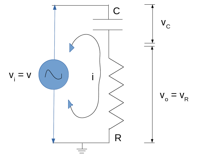
Capacitor Resistor Series Circuit – High Pass Filter
Filter Design
Now in the amplification formula, observe that the minimum amplification is zero at zero frequency i.e. at DC, and keeps on increasing with frequency, reaching one, at infinite frequency. But practically, one can’t reach infinity. Hence, for practical purposes, the amplification is considered good enough at a value of 1/√2, which happens when ω * R * C = 1, meaning at frequency = 1/(2 * π * R * C}, which is often referred as the cut-off frequency. And for practical purposes, the currents of frequencies below this are cut-off, only allowing the ones above it. Note that, by controlling the values of R & C, one can beautifully control the cut-off frequency.
Now, this current passing through the resistor R gives the voltage vR across the resistor as R * i. Thus, this voltage also follows the same cut-off. So, if one considers the voltage v as input and the voltage vR as output, that gives a high pass filter (HPF), which passes the frequencies above the cut-off and (practically) blocks the ones below it.
Interestingly enough, if the positions of R & C are swapped (as shown in figure below), and the voltage vC across the capacitor is considered as output, it would become a low pass filter (LPF), which passes the frequencies below the cut-off and (practically) blocks the ones above it. Why? Because the amplification factor there is as follows:
}^{2}}}") , where ω = 2 * π * frequency
, where ω = 2 * π * frequency
With this, Pugs have got the two simplest RC filters.
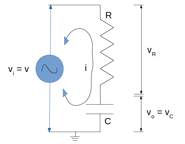
Resistor Capacitor Series Circuit – Low Pass Filter
Filter Application
Now, for proper sine wave, most importantly Pugs wanted to remove the PWM carrier frequency, which is way higher than his various waveform frequencies of 1 & 2 KHz. So, Pugs would need a low pass filter, which passes 1KHz, 2KHz but filters out the high PWM carrier frequency. A 5KHz cut-off frequency for the filter seems okay. So, let’s compute the values of R & C for it. As per the formula, R * C = 1/(2* π * frequency) = 1/(2* π * 5000) = 31.831 * 10-6s. Assuming a value of 1K ohms for R, C could be chosen as the standard 33 nano farads. Using these two selections, Pugs computed back the cut-off frequency, which turned out to be 4.8KHz – that’s fine for Pugs.
Taking a 1K resistor and a 33 nF capacitor, Pugs connected them in series across his sine wave output.
Pugs then checked the output between RC joint and GND, on the home-made PC oscilloscope, as created in his previous PC Oscilloscope article. It showed up the sine wave as in his previous article but now with almost no carrier frequency zigzags, though the amplitude was a bit reduced.
Next Article >>